TOC

TOC

G-5

ELECTRICAL DIAGRAMS

G-5

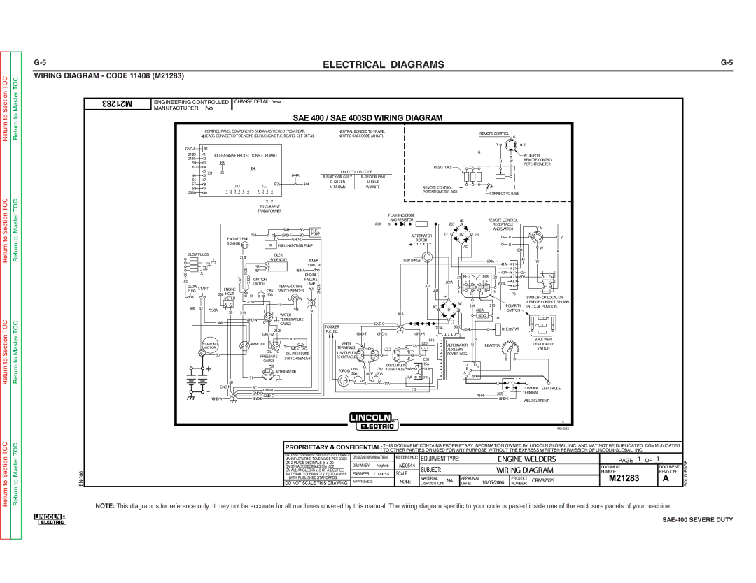
WIRING DIAGRAM - CODE 11408 (M21283)


Return to Section

Return to Section TOC

Return to Section TOC

Return to Section TOC

Return to Master

Return to Master TOC

Return to Master TOC

Return to Master TOC

EN-166

M21283

ENGINEERING CONTROLLED


CHANGE DETAIL: New


MANUFACTURER: No


SAE 400 / SAE 400SD WIRING DIAGRAM


CONTROL PANEL COMPONENTS SHOWN AS VIEWED FROMREAR.


NEUTRAL BONDED TO FRAME.


REMOTE CONTROL


*LEADS CONNECTED TO ENGINE IDLER/ENGINE P.C. BOARD, SEE DETAIL

NEUTRE RACCORDE AU BATI.


G


Y


X


GND-A

B1


G


212D

1

IDLER/ENGINE PROTECTION P.C. BOARD


PLUG FOR


212C

2


B3


U

W

REMOTE CONTROL


59

3


POTENTIOMETER


61

4


B4


RESISTORS


44

5

J31

55


844A


LEAD COLOR CODE


6


B-BLACK OR GREY

R-RED OR PINK


54

7


G-GREEN


U-BLUE


57

8


J33


J32


B2


844


N-BROWN


W-WHITE


REMOTE CONTROL


58

9


1

2

5

6

1

4


238A

10

3

4

2

3


POTENTIOMETER BOX


CONNECT TO BASE


TO CURRENT


TRANSFORMER


FLASHING DIODE


238

AND RESISTOR


203

AC


REMOTE CONTROL


RECEPTACLE


G


58H


FUEL


AND SWITCH


(-)

D2


(+)


X


ENGINE TEMP.

*58


GND-F


PUMP


ALTERNATOR


B


Y


GND-D


ROTOR

-


SENSOR


FUEL INJECTION PUMP


+


AC


R


W


600


R


GLOW PLUGS


IDLER


212F


41


SOLENOID


IDLER


SLIP RINGS


600A


W


*55


B


SWITCH


41A

1


212E


W


*844A


2


*57


R


42A

42


ENGINE


*212C

*212D


21 NEG

POS 22


4

602


PLUG START

ENGINE


CB5


SWITCH/SENDER


*61

B-GND


201


1


4


53


IGNITION


FAILURE


201A

-


+

602A

5


GLOW


SWITCH


TEMPERATURE

LAMP


202


6


238 HOUR


56


10A


(+)


3

2


P8


SWITCH FOR LOCAL OR


METER


G

W


212A


+

-


43


AC

214


215

POLARITY

REMOTE CONTROL SHOWN


50B

52


AC


IN LOCAL POSITION.


*44


D1


*238A

5B


51A


S


5C


602A


SWITCH


I


41A


WATER


500


50A


GND-N

G


TEMPERATURE


GND-C


(-)


1


GAUGE


2

4

3


TO IDLER


203A

602C


RHEOSTAT


212B


P.C. BD.


602B


GND-M


GND-T

GND-S

GND-R


4


5


200


N


BACK VIEW


AMMETER


S


I


WHITE


820

810


STARTING


+

-


*54


7A


ALTERNATOR U


REACTOR


OF POLARITY


MOTOR


OIL

G

WK G


TERMINALS


AUXILIARY


SWITCH


S


50


OIL PRESSURE

115V DUPLEX


POWER WDG.


B


PRESSURE


RECEPTACLE


SWITCH/SENDER


CB1


+


GAUGE


15A


*59


4A

230V DUPLEX


F


ALTERNATOR


TOROID

CB3

CB2 RECEPTACLE 6A

11A


E


B+ D+


20A

400F

20A

7A


A 2


5B


51


810


1


11

11A


GND-N


5C


TO WORK ELECTRODE


GND-B


11B


-*GND-A


2CR


TERMINAL


GND-D


*844


GND-E GND-C


GND-E


WELD CURRENT


A


M21283


PROPRIETARY & CONFIDENTIAL:THIS DOCUMENT CONTAINS PROPRIETARY INFORMATION OWNED BY LINCOLN GLOBAL, INC. AND MAY NOT BE DUPLICATED, COMMUNICATED


UNLESS OTHERWISE SPECIFIED TOLERANCE


TO OTHER PARTIES OR USED FOR ANY PURPOSE WITHOUT THE EXPRESS WRITTEN PERMISSION OF LINCOLN GLOBAL, INC.


DESIGN INFORMATION

REFERENCE:

EQUIPMENT TYPE:


ENGINE WELDERS

PAGE _1_ OF 1_


MANUFACTURING TOLERANCE PER E2056


ON 2 PLACE DECIMALS IS ± .02

DRAWN BY:

Maglietta

M20544


ON 3 PLACE DECIMALS IS ± .002

SUBJECT:


WIRING DIAGRAM

DOCUMENT

DOCUMENT


MATERIAL TOLERANCE (" t ") TO AGREE

ENGINEER:

C. KOCSIS

SCALE:


NUMBER:

REVISION:


ON ALL ANGLES IS ± .5 OF A DEGREE


M21283

A


WITH PUBLISHED STANDARDS.

APPROVED:


NONE

MATERIAL

NA

APPROVAL


PROJECT

CRM37526


DO NOT SCALE THIS DRAWING


DISPOSITION:


DATE:

10/05/2006


NUMBER:


SOLID EDGE

NOTE: This diagram is for reference only. It may not be accurate for all machines covered by this manual. The wiring diagram specific to your code is pasted inside one of the enclosure panels of your machine.

®

SAE-400 SEVERE DUTY

Page 134
Image 134
Lincoln Electric SVM187-A service manual M21283

SVM187-A specifications

The Lincoln Electric SVM187-A is a cutting-edge welding machine designed for professional welders and industrial applications. Known for its reliability and performance, it stands out in the competitive welding equipment market. This versatile machine is structured to handle various welding processes, making it a popular choice among users.

One of the primary features of the SVM187-A is its multifunctional capabilities. It supports MIG, TIG, and Stick welding, allowing users to switch between different welding techniques seamlessly. This flexibility makes it suitable for diverse applications, whether working on automotive repairs, metal fabrication, or construction projects. Additionally, the machine is equipped with a robust power output, ranging from low to high amperage settings, enabling users to tackle a wide array of materials, including mild steel, stainless steel, and aluminum.

The SVM187-A incorporates advanced inverter technology, which ensures increased efficiency and reduced energy consumption. This technology leads to a more compact design, making the unit portable and easy to transport. The lightweight construction of the machine does not compromise its durability; it is built with high-quality materials to withstand the rigors of a professional workshop.

Another notable characteristic of the SVM187-A is its user-friendly interface. The intuitive control panel includes digital displays for precise settings adjustments, ensuring accuracy during operation. Beginners and seasoned welders alike can benefit from the clear and straightforward design, reducing training time and enhancing productivity.

Safety features are paramount in the SVM187-A's design. The machine is equipped with thermal overload protection, ensuring that it operates within a safe temperature range to prevent damage and promote longevity. Additionally, it features automatic voltage regulation, which maintains a stable arc even under varying input voltage conditions.

In summary, the Lincoln Electric SVM187-A is a versatile, efficient, and user-friendly welding machine suited for both professional and industrial applications. Its multifunctionality, inverter technology, and robust safety features set it apart from competitors, making it a reliable choice for welders seeking to elevate their craftsmanship while ensuring safety and efficiency. This machine represents the innovation and quality that Lincoln Electric is renowned for in the welding industry.