to Section TOC

to Master TOC

E-2

THEORY OF OPERATION

E-2


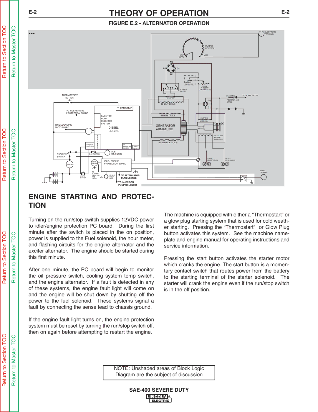
FIGURE E.2 - ALTERNATOR OPERATION


---


ELECTRODE


TERMINAL


OUTPUT


CONTROL


MIN

MAX


(OFF)


THERMOSTART

BUTTON

TO IDLE / ENGINE

PROTECTION BOARD

TO IDLE/ENGINE

PROT. BOARD

S

T

A

R

STARTER T

SOLENOID E

R

RUN/STOP

IDLE SWITCH

SWITCH


THERMOSTAT

INJECTION

PUMP

SOLENOID

SYSTEM

DIESEL

ENGINE

OIL

PRESSURE TEMP

SWITCH SWITCH

IDLE

SOLENOID

AC


(-)

(+)


AC


REMOTE


RHEOSTAT

LOCAL


POLARITY

RHEOSTAT


(JOB SELECTOR)


SWITCH


RESISTOR


FLASHING

TO HOUR METER


(+)


RESISTOR AND


SHUNT COILS


DIODE


(-)


SERIES COILS


EXCITER


WINDING

(-)

(+)


GENERATOR


EXCITER


ARMATURE


ROTOR


AUXILIARY

POWER

WINDINGS

INTERPOLE COILS

115 VAC

230 VAC

to

to


HOUR

IDLE / ENGINE

AMMETER

METER

PROTECTION BOARD

RECEPTACLES

RECEPTACLES


TO


WORK


TERMINAL


FLASHING

ENGINE

TO ALTERNATOR

START

RESISTOR

AND

FAULT


BUTTON

FLASH/SENSE

DIODE

LIGHT

TO INJECTION

PUMP SOLENOID

Return to Section TOC

Return to Master TOC

ENGINE STARTING AND PROTEC- TION

Turning on the run/stop switch supplies 12VDC power to idler/engine protection PC board. During the first minute after the switch is placed in the on position, power is supplied to the Fuel solenoid, the hour meter, and flashing circuits for the engine alternator and the exciter alternator. The engine should be started during this first minute.

After one minute, the PC board will begin to monitor the oil pressure switch, cooling system temp switch, and the engine alternator. If a fault is detected in any of these systems, the engine fault light will come on and the engine will be shut down by shutting off the power to the fuel solenoid. These systems signal a fault by connecting the sense lead to chassis ground.

If the engine fault light turns on, the engine protection system must be reset by turning the run/stop switch off, then on again before attempting to restart the engine.

The machine is equipped with either a “Thermostart” or a glow plug starting system that is used for cold weath- er starting. Pressing the “Thermostart” or Glow Plug button activates this system. See the machine name- plate and engine manual for operating instructions and service information.

Pressing the start button activates the starter motor which cranks the engine. The start button is a momen- tary contact switch that routes power from the battery to the starting terminal of the starter solenoid. The starter will crank the engine even if the run/stop switch is in the off position.

Return to Section TOC

Return to Master TOC

NOTE: Unshaded areas of Block Logic Diagram are the subject of discussion

SAE-400 SEVERE DUTY

Page 32
Image 32
Lincoln Electric SVM187-A service manual Theory of Operation, Engine Starting and PROTEC- Tion

SVM187-A specifications

The Lincoln Electric SVM187-A is a cutting-edge welding machine designed for professional welders and industrial applications. Known for its reliability and performance, it stands out in the competitive welding equipment market. This versatile machine is structured to handle various welding processes, making it a popular choice among users.

One of the primary features of the SVM187-A is its multifunctional capabilities. It supports MIG, TIG, and Stick welding, allowing users to switch between different welding techniques seamlessly. This flexibility makes it suitable for diverse applications, whether working on automotive repairs, metal fabrication, or construction projects. Additionally, the machine is equipped with a robust power output, ranging from low to high amperage settings, enabling users to tackle a wide array of materials, including mild steel, stainless steel, and aluminum.

The SVM187-A incorporates advanced inverter technology, which ensures increased efficiency and reduced energy consumption. This technology leads to a more compact design, making the unit portable and easy to transport. The lightweight construction of the machine does not compromise its durability; it is built with high-quality materials to withstand the rigors of a professional workshop.

Another notable characteristic of the SVM187-A is its user-friendly interface. The intuitive control panel includes digital displays for precise settings adjustments, ensuring accuracy during operation. Beginners and seasoned welders alike can benefit from the clear and straightforward design, reducing training time and enhancing productivity.

Safety features are paramount in the SVM187-A's design. The machine is equipped with thermal overload protection, ensuring that it operates within a safe temperature range to prevent damage and promote longevity. Additionally, it features automatic voltage regulation, which maintains a stable arc even under varying input voltage conditions.

In summary, the Lincoln Electric SVM187-A is a versatile, efficient, and user-friendly welding machine suited for both professional and industrial applications. Its multifunctionality, inverter technology, and robust safety features set it apart from competitors, making it a reliable choice for welders seeking to elevate their craftsmanship while ensuring safety and efficiency. This machine represents the innovation and quality that Lincoln Electric is renowned for in the welding industry.