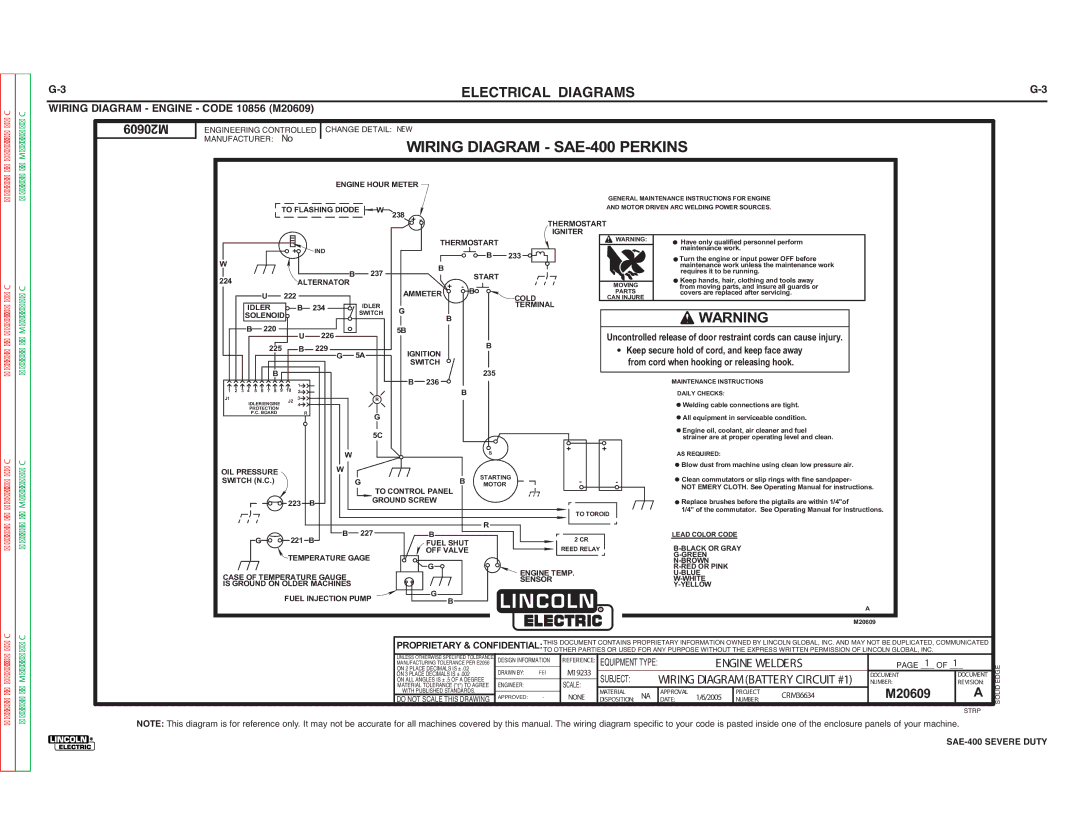
Lincoln Electric SVM187-A service manual Wiring Diagram SAE-400 Perkins

Models: SVM187-A

1 142
Download 142 pages 41.75 Kb
Page 132
Image 132

Return to Section TOC

Return to Section TOC

Return to Section TOC

Return to Section TOC

Return to Master TOC

Return to Master TOC

Return to Master TOC

Return to Master TOC

G-3


ELECTRICAL DIAGRAMS


G-3

WIRING DIAGRAM - ENGINE - CODE 10856 (M20609)


M20609

ENGINEERING CONTROLLED CHANGE DETAIL: NEW


MANUFACTURER: No


WIRING DIAGRAM - SAE-400 PERKINS


ENGINE HOUR METER


GENERAL MAINTENANCE INSTRUCTIONS FOR ENGINE


TO FLASHING DIODE W

238 +


AND MOTOR DRIVEN ARC WELDING POWER SOURCES.


-


THERMOSTART


IGNITER

WARNING:


THERMOSTART


Have only qualified personnel perform


+

IND


B

233


maintenance work.


Turn the engine or input power OFF before


W


B


maintenance work unless the maintenance work


B

237


START


requires it to be running.


224


ALTERNATOR


+

-


MOVING


Keep hands, hair, clothing and tools away


B


from moving parts, and insure all guards or


U

222


AMMETER


COLD


PARTS


covers are replaced after servicing.


CAN INJURE


IDLER


B

234

IDLER

G

B


TERMINAL


WARNING


SOLENOID


SWITCH


B

220


U

226


5B


Uncontrolled release of door restraint cords can cause injury.


225


B


B

229

5A

IGNITION


Keep secure hold of cord, and keep face away


G


from cord when hooking or releasing hook.


B


SWITCH


235


B 236


MAINTENANCE INSTRUCTIONS


1 2 3 4

5 6 7 8 9

10

1


B


2


DAILY CHECKS:


J1


J2

3


R


Welding cable connections are tight.


PROTECTION


4


IDLER/ENGINE


P.C. BOARD


R


G


All equipment in serviceable condition.


5C


Engine oil, coolant, air cleaner and fuel


strainer are at proper operating level and clean.


W


S


+

+


AS REQUIRED:


OIL PRESSURE


W


Blow dust from machine using clean low pressure air.


STARTING


SWITCH (N.C.)


G


B


-

-


Clean commutators or slip rings with fine sandpaper-


MOTOR


TO CONTROL PANEL


NOT EMERY CLOTH. See Operating Manual for instructions.


223

B

GROUND SCREW


Replace brushes before the pigtails are within 1/4"of


TO TOROID


1/4" of the commutator. See Operating Manual for instructions.


B

227


B


R


LEAD COLOR CODE


G


221 B


FUEL SHUT


2 CR


B-BLACK OR GRAY


OFF VALVE


REED RELAY


TEMPERATURE GAGE


G-GREEN


G


N-BROWN


ENGINE TEMP.


R-RED OR PINK


CASE OF TEMPERATURE GAUGE


U-BLUE


SENSOR


W-WHITE


IS GROUND ON OLDER MACHINES


G


Y-YELLOW


FUEL INJECTION PUMP


B


A


R


M20609


PROPRIETARY & CONFIDENTIAL:THIS DOCUMENT CONTAINS PROPRIETARY INFORMATION OWNED BY LINCOLN GLOBAL, INC. AND MAY NOT BE DUPLICATED, COMMUNICATED


UNLESS OTHERWISE SPECIFIED TOLERANCE


TO OTHER PARTIES OR USED FOR ANY PURPOSE WITHOUT THE EXPRESS WRITTEN PERMISSION OF LINCOLN GLOBAL, INC.


DESIGN INFORMATION

REFERENCE:

EQUIPMENT TYPE:


ENGINE WELDERS

PAGE _1_ OF 1_


ON 2 PLACE DECIMALS IS ± .02


MANUFACTURING TOLERANCE PER E2056


EDGE


ON ALL ANGLES IS ± .5 OF A DEGREE

DRAWN BY:

FEI

M19233


ON 3 PLACE DECIMALS IS ± .002


SUBJECT:

WIRING DIAGRAM(BATTERY CIRCUIT #1)

DOCUMENT

DOCUMENT


MATERIAL TOLERANCE ("t") TO AGREE

ENGINEER:

-

SCALE:

NUMBER:

REVISION:

SOLID


DO NOT SCALE THIS DRAWING

APPROVED:

NONE

DISPOSITION: NA

DATE:

1/6/2005

NUMBER:

CRM36634

M20609

A


WITH PUBLISHED STANDARDS.


MATERIAL

APPROVAL

PROJECT


STRP

NOTE: This diagram is for reference only. It may not be accurate for all machines covered by this manual. The wiring diagram specific to your code is pasted inside one of the enclosure panels of your machine.

®

SAE-400 SEVERE DUTY


Page 132
Image 132
Lincoln Electric SVM187-A service manual Wiring Diagram SAE-400 Perkins

SVM187-A specifications

The Lincoln Electric SVM187-A is a cutting-edge welding machine designed for professional welders and industrial applications. Known for its reliability and performance, it stands out in the competitive welding equipment market. This versatile machine is structured to handle various welding processes, making it a popular choice among users.

One of the primary features of the SVM187-A is its multifunctional capabilities. It supports MIG, TIG, and Stick welding, allowing users to switch between different welding techniques seamlessly. This flexibility makes it suitable for diverse applications, whether working on automotive repairs, metal fabrication, or construction projects. Additionally, the machine is equipped with a robust power output, ranging from low to high amperage settings, enabling users to tackle a wide array of materials, including mild steel, stainless steel, and aluminum.

The SVM187-A incorporates advanced inverter technology, which ensures increased efficiency and reduced energy consumption. This technology leads to a more compact design, making the unit portable and easy to transport. The lightweight construction of the machine does not compromise its durability; it is built with high-quality materials to withstand the rigors of a professional workshop.

Another notable characteristic of the SVM187-A is its user-friendly interface. The intuitive control panel includes digital displays for precise settings adjustments, ensuring accuracy during operation. Beginners and seasoned welders alike can benefit from the clear and straightforward design, reducing training time and enhancing productivity.

Safety features are paramount in the SVM187-A's design. The machine is equipped with thermal overload protection, ensuring that it operates within a safe temperature range to prevent damage and promote longevity. Additionally, it features automatic voltage regulation, which maintains a stable arc even under varying input voltage conditions.

In summary, the Lincoln Electric SVM187-A is a versatile, efficient, and user-friendly welding machine suited for both professional and industrial applications. Its multifunctionality, inverter technology, and robust safety features set it apart from competitors, making it a reliable choice for welders seeking to elevate their craftsmanship while ensuring safety and efficiency. This machine represents the innovation and quality that Lincoln Electric is renowned for in the welding industry.