G-7 | | | | | | | | | | | | | | | | | | | | | | | | | | | | | | | | ELECTRICAL DIAGRAMS | | | | | | | | | | | | | | | | | | | | | | | | | | | G-7 |
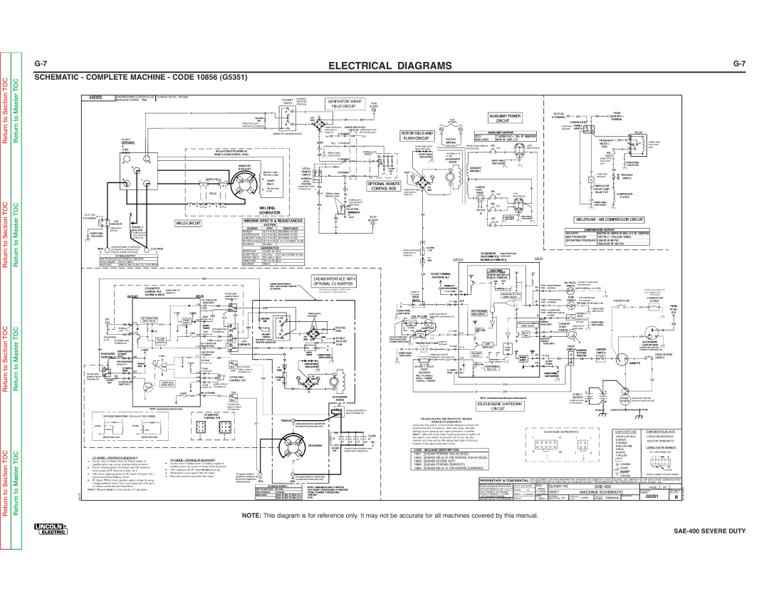
SCHEMATIC - COMPLETE MACHINE - CODE 10856 (G5351) | | | | | | | | | | | | | | | | | | | | | | | | | | | | | | | | | | | | | | | | | | | | | | | | |
G5351 | | ENGINEERING CONTROLLED | CHANGE DETAIL: Revised | | | | | | | | | | | | | | | (SHOWN IN | | | | | | | | | | | | | | | | | | | | | | | | | | | | | | | | | | | | | | | | | |
| | MANUFACTURER: Yes | | | | | | | | | | | | | | | | | | POLARITY | | | | GENERATOR SHUNT | | | | | | | | | | | | | | | | | | | | | | | | | | | | | | | | | | |
| | | | | | | | | | | | | | | | | | | NEGATIVE | | | | | | | | | | | | | | | | | | | | | | | | | | | | | | | | | | | | | |
| | | | | | | | | | | | | | | | | | | | | | | | | SWITCH | POISTION) | | | | FIELD CIRCUIT | TO D1 | | | | | | | | | | | | | | | | | | | | | | | | | | | | | | | | | | |
| | | | | | | | | | | | | | | | | | | | | | | | | | | | | | | | AC POST | | | | | | | | | | | | | | | | | | | | | | | | | | | | | | | | | | |
| | | | | | | | | | | | | | | | | | | | | | | | | | 4 | | R | | | | | | | | | | | | | | | | | | | | | | | | | | | | | | | | | | | | | | | | | |
| | | | | | | | | | | | N | | | | | | | | | | | | Y | | 2 | | | | | | | | | | | | | | | | | | | | | | | | | | | TO PC BD | | | | | | | FROM | | | | | | |
| | | | | | | | | | | | | | | | | | | | | | | | | | | | | | | | | | | | | | | | | | | AUXILIARY POWER | | | | | | 242 | 240 | | | | | | | |
| | | | | | | | | | | | | | | | | | | | | 500 OHMS | | | | | | 35A | | | | | | | | | | | | | | | | | | | R-TERMINAL | | | HOUR MTR + | | | | | | |
| | | | | | | | | | | | | | | | | | | | | 50W | | | | | | 800V | | - | | W | 203 | | | | | | | TO D1 | | | | | CIRCUIT | | | | | | | | COMPRESSORR | B | TERMINAL | | | | | | |
| | | | | | | | | | | | | | | | | | | | located behind upper | | | | 1 | | B | | + | D2 | | | | | | | | | | AC POSTS | | | | | | | | | | | | | | | | | | | |
| | | | | | | | | | | | U | | | | | | | | control panel on reactor box | U | | | | | | | | located behind upper | REMOTE RECEPTACLE | | | | | | | | | | | | | | | | | | | | loacted lower | ENABLE | | | | | | | | | |
| | | | | | | | | | | | | | | | | | | | | | | | 3 | | | | | | control panel on | AND PLUG located lower Lt hand | | | | | | | | | | | | | | | | | | | | front panel | SWITCH | | | | | | | | | |
| | | | | | | | | | | | | | | | | | | | | | | | CENTER OFF =NO WELD OUTPUT | | | | reactor box | X-TERMINAL | side of control panel | ROTOR FIELD AND | | | OCV | AUXILIARY OUTPUT | | | | | | | | | | | | | | 85 | RELAY | | | |
| | | | | | | | | | | | | | | | | | | | | | | | | | | | | | | R | n.c. | B | X | n.c. | | FLASH CIRCUIT | EXCITER | | | | 115/230 VAC + 10% @ 1800RPM | | | | | | | | | Y | | | 30 | | | | | |
| | | top right of | | | | | | | | | | | | | | | | | | | | | | | | | | | | | | | | | | | MAX LOAD | | 3KW @ 100% D.C. | | | | | | | | | | | FROMAM- | 239 | B | | | | | |
| | | generator frame | | | | | | | | | | | | | | | | | | | | | | | | | | 600A | P8-1G-TERMINAL | | | | | | | | WINDING | | | | | | | | | | | | | | no | located behind | | |
| | | GENERATO | | | | | | | | | | | | | | | | | | | | | | | | | | | | | | | | | | alternator &rotor located at | 15A | | | | | 230V | | | | | | | | | | METER + | | 87a | | lower control | | |
| | | R | | | | | | | | | | | | | | | | | | | | | | | | | | | | P8-2 | 41A | 41 | G | G | | | diodes located behind | | | CB2 | | | | | | | | | | | | POST | B | 87 | | | panel | | |
| | | LEAD | | | | | | | | | | | | | BRUSH POSITION SHOWN AS | | | | | | | | | | | | | 64ohms +/- 6.4 | | | upper control panel | | | end of generator | | | | | RECEPTACLE | | | | | | | | | | | 86 | | | | | |
| | | BLOCK | | | | | | | | | | | | | | | | | | | | | | | UPPER PANEL | | | | | | | | 41.5 ohms +/- 1.0 | R | | | | B | | | B | | | | | | | | | | | 10A | | | | | | |
| | | | | | | | | | | | | | | VIEWED FROMCONTROL PANEL | | | | | | | | | | 600 | | 150 W | | | | UPPER PANEL | | | | | | | | | | | | | | | | | | | | | | |
| | | | | | | | | | | | | | | | | | | | | | | | | GND SCREW | | | | | @ 25C | | | | | | | | | | | | | | | | | | | | FUSE | | | | | | | |
| | | | | | | | | | | | | | | | | | | | | | | | | | | | | | | | | | | cc | | | | GND SCREW | | | | | | | | | | | | | | | | | | | | G | | | | | |
| | | | | | | | | | | | | | | | | | | | | | | | | | | | | | | | | Y-TERMINAL | w | | | | | | | ALTERNATOR | | | UPPER PANEL | G | | | | | | | | | | | | located behind | | | | | |
| | | E | | | | | F | | | | | | | | | | | | | | | | | | | | | | | | | | Y | U | | | | | | | ROTOR | | | | | | | | | | | | | | | lower control | | LOWER PANEL | | | |
| | | | | | | | | | | | | | | | | | ARMATURE | | | | | | | | | | | R | | | max | | | | | | | | | | | GND SCREW | | | | | | | | | | | | | panel | | B | GND SCREW | | | |
| | | | 2 | | | | | | | | | | | | | | | | | | | | | LOCAL/ | | | R | n.c. | | | 25OHM | | | | | | | | AUXILIARY | | | | | | | | | | | | | | | | | | | | | | |
| | | | | | | | | | | | | | | | | | & BRUSHES | | | | | | | | | | | | | | | R | | | | | | | | | | | | | | | | | | | | 243 | | | | | | |
| | | | | | | | | | | | | | | | | | | | | MIN rheo=54vdc | | | REMOTE | | | | W-TERMINA | | 50W | 140vdc | | | | | | WINDINGS | | | | | | | | | | | | | | | | | | | | | | | |
| | | | | | | | | | | | | | | | | | | | | | | | | | | | | | | | | | | | | | | | | | | | | | | | | | | loacted lower | | | | | | | |
| | | | | | | | | | | | | | | | | | | | | | | MAX rheo=140vdc | | | SWITCH | | | W | L | W | W | x3 | | | | - | | | | | | | | | | | | | | | | | | | | PRESSURE | | | | |
| | | | | | | | | | | | | | | | | | | | - | + | | | | | | | | | | | | | | | | | | | | | | | | | | | | | front panel | | | | |
| | | A | | | 1 | | | | | | | | SERIES FIELD | | | | | N | SHUNT | | | | (SHOWN IN | | | | | | | | | | | | W | | | | | | | | | | | | | | | | | G | | SWITCH | | | | |
| | | | | | | | | | | | | | | | | | | | | | | LOCAL | | | | 42 | OPTIONAL REMOTE | | | | D1 | | | | | | | | | | | | | | | | | | | | G | | B | | | | | | |
| | | | | | | | | | | | | | N | | | N | | | | | | | FIELD | | | | POSITION) | | | | | | | | | | | | | | | | | | | | | | | | | | COMPRESSOR | | | | | | |
| | | | | | | | | | | | | | | | | | + | - | | | 38.2-40.6 ohms | | located lower middle | 602 | | | | CONTROL BOX | | | | | 35A | | | CURRENT | | | | | | | W | | | | | | | | | | | | | | | | |
| | | | | | | | | | | | | | | | | | | | | N | | of control panel | | | | P8-3 | located behind upper | + | 800V | | | SENSE | | | | | | | | | | | | | | | | CIRCUIT LAMP | | | | | | | |
| | | | | | | | | | | | | | | POLES | | | | | | @ 25C | | | | | | | P8-4MIN rheo=86vac | 42 | | | control panel | on | | | B | | TOROID | | 20A | CB4 | | 115V | | | | | | | | | | | B ON=ACTIVE | COMPRESSOR | | | | |
| | | | | | | | | | | | | | | | | | | | | | | | | | | | | | | | MAX rheo=0vac | | | reactor box | | | | | | | | | | RECEPTACLE | | | | | | | | | | | | | | | |
| | | | | | | | | | | | | | | | | | | | | | | | | | | | | | | | A | | | | | | | | | | B | | | | B | | | | | | | | | | | | | CLUTCH | | | | | |
| | | | | | | | | | | | | | | | | | | | | | | | | | | | | | | | | | | | | | | | | | | | | | | | | | | | | | | | | | 241 | | | | | | |
| | | | | | | | | | | | | | | | | | | | | | | | | | | | | | | | | | located upper Lt | | | | | | | | | | | | | | | | | | | | | | | | | | | | | | | | | |
| | | | | | | | | | | | | | | | | | | | | | | | | | | | | | | 602 | | | W hand side behind | | | | | | | | | | | 20A | | | | | | | | | | | | | | | LOWER PANEL | | | | | | | |
| | | | | | | | | | | | S | N | S | S | N S | | | | | | | | | | | | | | | max | control panel | | | | | | | | | | B | CB3 | | | | | | | | | | | | | | GNDSCREW | | | | | | | |
| | | | | | | | | | | | | | | | | WELDING | | | | | | | A | | JOB | | | | | | | | | | | | | | | | | | | | | | | | | | | | | | | | | |
| | | | | | | | | | | | | | | | | | | | | | | | | | | | | | cc | SELECTOR | | | | | | | | | TO PCB | | | | B | | | G | | | | | | | | | | | | | | | | | | |
| | | | | | | | | | | | | | | | | | | | | | | GENERATOR | | | | | | | | 64RHEOohmsST+/-AT | | | | | | | | | | | | | | | | | | | | | | | | | | | | | | | |
TO PC BD | | | | | | | | | | | | | | | | | | | | | | | | | | | | | | w | | | | | 201 | | | J2 | | | | | | | | | | | | | | | | | | | | | | | | | |
| | | | | | | | | | | | | | | | | | | | | | | | | | | | | | | | | 6.4 | TO D1 | | | | | | | | | | | | G | | UPPER PANEL | | | | | | | | | | | | | | | | | | |
R-TERMINAL | | | | | | | | | | | | | | | | | | | | | | | | | | | | | | | | | 602 | 150 W | | | | | | | | | | B | 15A | | UPPER PANEL | GND SCREW | | | | | | | | WELD'N AIR - AIR COMPRESSOR CIRCUIT | | | |
| 2 CR | | | | | | | | | | | | | | | | | WINDING SPEC'S & RESISTANCES | | | U | | | AC POST | | | | | | | | | | | GND SCREW | | | | | | | | | | |
| | | | | | | | | WELD CIRCUIT | | | | | | | | | | B | | | | | | | | | | | | | CB1 | | | | | | | | | | | | | | | | | | | | | | |
| | REEDRELAY | VARIABLE | | | | | | | | | | | | | | EXCITER | | | | | | | | | | | | | | | | | | | | | | | | B | | | | | | | | | | | | | | | | | | | | | |
| | located behind | | | | | | | | | | | | | | | | | | | | | | | | | W | | | | | | | B | | | | | | | | | | | | | | | | | | | | | | | | | | | | |
| | | | | | | | | | | | | | | | WINDING | | | SPEC | RESISTANCE | | | | | | | | | | | | | | | | | | | | | | | | | | | | | | | COMPRESSOR OUTPUT | | | | | | |
| | work stud | | REACTOR | | | | | | | | | | | | | | POWER | | ALT-214-3C .230 OHMS @ 25C | | | | | | | | | | | | | | | | | | | | | | | | | | | | | | | | | | | | | | |
LOWER PANEL | | | | located upper Rt | | | | | | | | | | | | | | | | | | | | | | | | | | | | | | | | | | | | | | | | | | | DELIVERY | | 35CFM @ 100PSI @ 60% D.C.@ 1400RPM | | |
GND SCREW | | | | | hand side behind | | | | | | | | | | | | | QUADRATURE | ALT-214-3B .560 OHMS @ 25C | | | | | | | | | | | | | | | | | | | | | | | | | | | | | | MAX PRESSURE | 150 PSI (11 GALLON TANK) | | | | |
| | | | | control panel | | | | | | | | | | | | | | AUXILIARY (TAIL) ALT-214-3D .424 OHMS @ 25C | | | | | | | | | | | | | | | | | | | | | | | | | | | | | | | | | |
| | | | | | | | | | | | | | | | | | | | ROTOR (4-POLE) ALT-214-3A 41.4+/-1.0 OHMS @ 25C | | | | | | | | | | | | | | | | | | | | | | | | | | | | | OPERATING PRESSURE LOADS @ 90 PSI | | | | | | |
| | output studs located on right fuel tank | | | | | | | | | | | | | | | DIAGRAM | | M14262 | | | | | | | | | | | | | | | | | | | | | | | | | | | | | | | | | | | | | UNLOADS @ 130 PSI | | | | | | |
WOR | | | | ELECTROD | | | | | | | | | | | | | GENERATOR | | | | | | | | | | | | | | | | 120 OHMS | | | | | | | | | | | | | | | | | | | | | | | | | | | | |
| rail (viewed from control panel end) | | | | | | | | | | | | | | | | | | | | | | | | | located behind upper | | 2.5W | | | | | | | | | | | | | | | | | | | | | | | | | | | | |
K | | (electrode closest to control panel) | | | | E | | | | | | | | | | | INTERPOLE | | S12261-25 | N/A | | | | | | | | | | | control panel on | | | | | | IDLER/ENGINE | located behind lower | | | | | | | | | | | | | | | | | | | |
| | CC WELD OUTPUT | | | | | | | | | | | | | | | SHUNT FIELD | | FKL-5AJ | 19.1-20.3 OHMS @ 25C | | | | | | | | reactor box | | | | | | | SHUTDOWN PCB control panel | | | | | | | | | | | | | | | | | | | | |
| | | | | | | | | | | | | | | | SERIES FIELD | FKL-420-U | N/A | | | | | | | | | | | | | | | | 1A | | | | | INPUTS | | | | | | | | | | | | | | | | |
MIN TO MAX OCV 57-97VDC @ 1800 RPM | | | | | | | | | | | | | | | | | | | | | | | | | | | | | OUTPUTS | (SCHEM. # L11006-2C1) | | | | | | | | | | | | | | | | | | |
| | | | | | | | | | | | | ARMATURE | | FKL-37.4M | N/A | | | | | | | | | | | | | | | | 1000V | | | | | | | | | | | | | | | | | | | | |
WELD RANGE | 80-575 AMPS | | | | | | | | | | | | | | | | | | | | | | | | | | | | | | | | | | | | | | | | | | | | | | | | | | | | | | | | | | |
MAX LOAD | 400A @ 40V @ 60% D.C. (1725 RPM) | | | | | | | | | | | DIAGRAM | | M5570 | | | | | | | | | | | | | | | | | | | | | | | | | | | | | | | | | | | | | | | | | | | | | |
| | | | | | | | | | | | | | | | | | | | | | | | | | | | | | | | | | | | | | | | | | | | | | 30 SEC TIMER | | +10v | | | | | | | | | | | | | | | | | | | |
| | | | | | | | | | | | | | | | | | | | | | | | | | | | | | | | | | | | | | | | 238 | TO EXC TERMINAL | | | (LOCKS OUT ENGINE | | +10V | | | | | | | | | | | | | | | | | | |
| | | | | | | | | | | | | | | | | | | | | | | | | | | | | | | | | | | | | | | | | Vbatt | SENSORS AND TIMES ALT | | | | | | | | | | | | | | | | | | | | |
| | | | | | | | | | | | | | 602 | | | | | | | | | | | | | | | | SAE400 INTERFACE WITH | | | | | | | ON ENGINE ALT | | | FLASH AT POWER-UP) | | | | | | | | | | | | | | | | | | | | |
| | | | | | | | | | | | | | | | | | | | | | | | | | | | | | | | | | | | | | | | reset | reset | | | | | | | | OIL PRESS | mounted on engine block | | | | | | | | |
| | | | | | | | | | | | | | | | | | | | | | | | | | | | | | OPTIONAL CV ADAPTER | | | | | | | | | | | | | | | | | | | | | | | | | | |
| | | | | | | | | | | | | | | | | | | | | | | | SHOWN FOR REFER ENCE | | | | | | | | | | | ENGINE ALT | | | | hi | lo | | | | | *10vdc =normal operation | belowfuel pump | | | | | | | | |
| | | | | | | CV ADAPTER | | | | | | | | | | | | | | | ONLY - NOT ACTUALLY PART OF | | | | | | | | | | | | | W | | | | | | | | | | | J1- | *0vdc | =shutdown | | | SWITCH | | | | | | | | | | | |
| | | | | | | | located inside CV | | | | | | | | | | | | | CV ADAPTER | | | | | | CV adapter box located on left fuel tank | | | | | | 224 FLASH & SENSE | | | | | reset | t | | | | | | SWITCH OPENS @ 15+/-3 PSI | | | | | | located engine starter side | |
| | | | | | | CONTROL PCB | | | | | | | | | | | | | | | | | | | | | | | located on | | | *11.5-12.9vdc | J1- | | | | | | | | | 7 | | B | 223 | | | | | | | | | | | | |
| | | | | | | | adapter box | | | | | | | S1 small switch | | | | | | | | | | | rail (viewed from control panel end) | | | | | | | | | ENGINE PROTECTION | | | | | | | | | | | | | | | at air intake manifold | | |
| | | OUTPUTS | | (SCHEM. # L6922) | | | INPUTS | | | | | | | | | | | | | | | | | | | | front panel | | | W | 3 | | | | | | | | | | | | | | | | | | | | | 1.0-2.0 ohms | | |
| | | | | | | | | | | | | located on face of | | | | | | | | | | | | | | | | | HOUR | | | | | | | | | | SENSE CIRCUIT | | | | | | | TEMP | | micro switch located | | | | | | THERMOSTART | |
| | | | | | | | | | | | | | | | | | CVadapter box | | | | | | | | | | | | | | | | | | | | | J1-1 | | | | | | | | | J1- | *10vdc =normal operation | | | | THERMOSTART | | | |
| | | | | | | | | | | | | | CR1 CONTACTOR | | | S1 | | | | | | | | | | | | | | | | | | METER | | | *11-13vdc | | | | | | + | | *0vdc | =shutdown | | | SWITCH | | in temp guage | | | | IGNITER | | |
| | | | | | | | | | | | | J1-8 | DRIVE INPUT | | | Ac | | | | | | | | | | | | | | | | | 5 | G | _ + | B | 229 | 0 | | | | | | - | | 6 | | B | | | | | TRIP POINT SET AT 220F +/- 4% | | | | | | | | |
| | | | | | | | | | | | | | | 608 | | | | | | | | | | | | | | | | | | | | | | | | | | 221 | | | | | G | | | | | B | 233 | | FROM | |
| | | | | | | | | | | | | | *140vdc | | | | | v | | | | 610 | | | | | | | | | | | | B | | | | | | | | | | | | | | +10v | | | *10vdc =noweldcurrent | | | | | | LOWER PANEL | | | | | PC BD | |
| | | | | | | | | | | | | | (J1-8 toJ1-4) | | | | vv | | | | | | | | | | | | | | | | | LOWER PANEL | | | | | | | FUEL SOLENOID | | | | | | | | | | | | | | GND SCREW | | | | | | | |
| | | | | | | | | | | +15VDC | +140VDC | | | | | | | | Y | | | | | | | | | | | | | | | | | | | | | | | | | | | *0vdc =weldcurrent, pick up | | | | | | | | | | | J1-3 | |
| | | | | | | | | | | | | | | | 610 | | | | | | | | 140vdc (w/ rheo- | | | | | GNDSCREW | | | | located engine left side | | DRIVE CIRCUIT | | | | | | | | | | 2 CR REED | | | | | | | | |
| | | | | | | | | | | | | 510 | | | | | | | | | | | | | | | | | | | | | | | | | | R | | to hiidle | | | | | | | | | | | | |
| CR1 | | | | | CR1 CONTACTOR | | | | | 140vdc | 510 | | | 500 OHMS | | | | | statatmax) | | | | | | | FUEL INJ PUMP (viewed from control panel end) | | | | | | | | | | | R | | | | RELAY | | | | | | | | | |
| | | | | | | POWER | J2-3 | (J2-3 toJ1-4) | | | | | | | 4 | R | | | | | | | | | | | | | | | | | | | | | | | | | | WELD | | | | located behind | | | | | | | | | |
| | | | | DRIVE CIRCUIT | | | | | | | | | | | 50W | | | | | | | | | | | | | | B | | | | Vbatt | | | | | | | | | | | | | | | | | | | | | |
| COIL | 606 | | J1-3 | | | | | | | SUPPLY | | | | | | | no | | | | | | 2 | | | | | | | | | | | SEC | | | | | | | | | | | WELD & AUX CURRENT | CURRENT | CURRENT | work stud | LOWER PANEL | | | | | | | 224 | |
| | | | | | | | | | | | | BOARD | | | | | | | | | | | | | | | | | | | | | | ENGINE TEMP B | | | | | | | | | | SENSE CIRCUIT | | SENSE INPUT | located behind | GNDSCREW | | | | | | | |
| | | 23-24vdc | | J1-7 | | | 25V | | | | | POWER | CR1 located inside | | 600 | | U | | | 1 | | | | | 203 | TO D1AC | | | 24ohms | | | *11-13vdc | | P-CHNL | | | | | | | | J2- | | W | SENSE | control panel | | B | | | | | | W | |
| | | inCV | | | | | | 2 AMP | | *0vdc | | CVadapter box | | | | | | | | | | + | | - | | POST | | | | | 4 ohms SWITCH | J1-9 | | | | | | | RECTI- | 3 | | TOROID | | | | | | | | | | |
| | | 605 | | | | | | | | | J2-2 | (J2-2 toJ1-4) | | | no | | | | POLARITY | | | B | D2 | | | | | | G | | | | B | 227 | | | | | | | | J2- | | | | | | | | | | | | | | | B | | |
| | | | | | | | | | | | | | | | | | | | | | TO P8-2 | | | | PRI | | | | | | | | | FIER | 4 | AUXILIARYW | | | | | | | | | | | B | 237 | | |
| 360-440 OHMS | | | | | | | EXC. OVER- | | | | | | 500 | | | | | | | SWITCH | 3 | | | 35A | | 600 | | FUEL INJ PUMP COILS G | | | | | | | +12v | | | | | | | | | | | | | | | | | | + | | |
| @ 25C | CR1 located inside | | | | | | VOLTAGE | | | | n.c. | 613 | | | | CR1 | (NO AFFECT W/CV | | | | 800V | | A | | TO PC BD | | DO NOTHAVE OVER- | ENGINE FAULT LAMP located on | | | | | | | | | | | CURRENT | | | | | | B | | | | | | ALTERNATOR | | |
| | CVadapter box | | | | | | PROTECTION | | | | CR1 CONTACTOR | | | no | ADAPTER HOOKED UP) | | | | | | 229 | | | CURRENT PROTECTION | | LAMP | | | rst | | | | SENSE INPUT | | | | | | | | | | | | |
| | | | | | | | | | | | | | DRIVE RETURN 600 | | | CONTACTS | | | | | | | | + _ | | | J1-10 | | | | | | | | front panel | | | | | | | | | | | IDLER | | | | | | | | 55AMP MAX DRAW | | |
602 | | | | | | +140VDC | | | | | | J1-4 | | | | | 612 | | | 238 | W | | | G | 5 | | | | 5C | G | | | R | U | *12-14vdc J1-4 | DRIVE CKT | | 12 SEC | | | | | | | | | | IGNITION | | | | located engine right side | | |
| | POWER OUTPUT | | | | | | | | ARC VOLTAGE | | | | | | | | | | | | | | | | B | | | | | | 226 | | | | | | TIMER | +10v | Vbatt | | | | | | SWITCH (SHOWN IN | | | | (viewfrom control panel end) | |
GENERATOR | | | | | | | | | | | | | | | | | | | | | | HOUR | | | | | | LOWER PANEL | | | | | | | IDLE DRIVE | reset | reset | | out | | | | | | | | AUTO IDLE | SWITCH | | | | | | | |
TO SHUNT | | | | | | | | | | | | | | | 611 | | | | | | | LOWER PANEL | | | | | | | located engine left side | | | | | J1- | | | | | | | | | | | START BUTTON | |
| | | | | +15VDC | | | J1-1 | FEEDBACK | | | | | | | | | | | | METER | | | | GNDSCREW | | | | | CIRCUIT | | hi | lo | | | | | *12-14vdc | | | | | POSITION) | | | | | | | |
SHUNT FIELD | FIELD | | J2-6 | | | | | | | | 667 | | | | | | | | | | | | | | | GNDSCREW | | | | | | | (viewed from control panel end) | J1-8 | | reset | | t | | POWER | 1 | 220 | | | | B | B | | | B | | SWITCH | |
| | | 509 | | | | | | | | | | | *8.6-42vdc | | | | | | | | | | W | | | | | | | | | | | | | | | | B | 225 | | | | | | SUPPLY | | | B | | | | | 236 | + | - | | | | |
| | *SEE WAVEFORM | | | | | | | | | | | | | c | | | | | | | | | | | | | | | | | | | | | | | | | | | | J1- | BOARD | | | | | | | | | | | | | |
| | (J2-6 toJ2-1) | | flywheel | | | | | | +15VDC | | (J1-1 toJ1-2) | | | | v | | | | | | | | | UPPER PANEL | | | | | | | | 10.5-12.5vdc | | | N-CHNL | | | | | | | | POWER | | | | | | | | | | AMMETER | | | |
S1C | | | | diode | | 74hz | PWM | | | | | | | | vv | S1 small switch | | | | 1A | | | GND SCREW | | | | | | | | 8.8 OHMS +/- .88 @25C | | | OVERCURRENT | | | | | 5 | | G | 5 | | | | | | | | | | | | | | |
| FLYWHEEL | | | | | | *12.9vdc | | | | | | | | | | | | | | | | | | J1- | | | | | | | | | | | | | | | | | B | | |
| vv | | DIODE | | J2-5 | | | | | | | | J1-5 | (J1-5 toJ1-2) | | | | S1D | located on face of | | | | 1000V | | | | | | | | | | | | | | | IDLER | FLYWHEEL | | PROT. CKT | | | | | | | | A | | | | | | | | | | | | | |
S1 small switch | c | | 503 | | | | | | | | | | 77 | max | | | | CVadapter box | | | | | | | | - | | | R | | | | | | | SOLENOID | DIODE | 2 | | | | | | | | | | LOWER PANEL | | | | | | | | | B | | | | | |
R3 | | J2-1 | | | | | | | | J1-6 | 10 | CV VOLTAGE | | | | 120 OHMS | | | | 35A | | | | | | | PULL TO LOWIDLE | | | | | | | | | | | | | | | | | | | | | | | | |
located on face of | v | 501 | | | | | | | | | 76 | | | | 567 | | | | | | | | | | | HI IDLE =1800RPM | | | | | | | | | | | | GND SCREW | | | | | | | | | | | | | | |
CVadapter box | 30 OHMS | | | | | | | | | | | cw | K | | CONTROL POT | | | | 2.5W | | | | 800V | | | | | | | | | | | | | | | | | | | | | | | | | | | | | | | | | 235 | | |
| CV SWITCH FOR | | | | | | SHUNT FIELD | | J1-9 | 75 | | | | | | | | | | | | | | | | | | | LOW IDLE =1100RPM | | | | | | | | | | | | | | | | | | | | | | | | | | | |
| 100W | | | | | | | located on face of | | | | | | | | | | D1 | | | | | | | | | | | | | | | U | | | | 222 | | | | | | | | | | | | | | | | | | | | |
| | | SHUNT FIELD | | | | | | | DRIVE CIRCUIT | | | *3.1vdc | | | | | | | B | | | | | | | | | | | | | | | | | | | | | | | | | | | | | | | | | | | | | | | | |
| | | | | | | | | | | | | | (J1-9 toJ1-2) | CVadapter box | | | | | | | 201 | | | | | | B | | | | | | | | | | | | | | | | | | | | | | | | | | | | | | | | | | | | | |
| | | | | | | | | | | | | | | | | | | | | | | | | | | | + | | | | | | | | | | | | | | B | | | | 234 | | | | | | | | | | | + | + | | | | | | | |
| | | | | | | | | | | 1/8 AMP | J1-2 | WELD COMMON | | | S1B | | | | | | | | | | | | | | | | | | | | | | | | | | | | | | | | | | | | | | | | | | | |
| | | | | | | | | | | | | | | 521 | | | c | | | | | | | | | | | | | ALTERNATOR | | | | | | | | | | | | | | | | | | | | | | | | 12 VOLT | | | | | | | | | |
| | | | | | | | | | | | | | | | | | v | | | | | | | | | | | | | | | | | | | | | | *NOTE : measurementmade with respecttoframeground. | | | | | | | BATTERY | | | ENGINE | located engine right side | | |
| | | | | | | | | | | | | | | | | | | | | | | | | | | | | | | | | | | | | | | | | | | | | | | | | |
| | | | | | | | | | | | | | | | | | | vv | | | | | | | | | | | | | | ROTOR | | | | | | | | | | | IDLER/ENGINE SHUTDOWN | | | | | | | located generator | | | STARTER (viewfrom control panel end) | | |
| | | | | | | | | | | | | | | | | | | S1 small switch | | | | | | | | | | | | | S2 | | | | | | | | | | | | | | | | | end of machine | | | | | | | | | |
| | | | | | | | *NOTE : measurementmade inCV mode. | | | | | | | | located on face of | | | | | | | | | | | | | | | | | | | | | | | | | | CIRCUIT | | | | | | | | | | | | | | | | | | | | | |
| | | | | | | | | | | | | | | CVadapter box | | | | | | | | | | | | | | S2 large switch located on | | | | | | | | | | | | | | | | | | | | | | | FRAME | ENGINE BLOCK | | | FRAME | | |
| | | | | | | | | | | | | | CV ADAPTER | | | | | | | | | | | | | | | | | | face of CVadapter box | | | | | | | | | | | | | | | | | | | | | | | | | | | | | | | | | | |
| VOLTAGE WAVEFORM : J2-6 to J2-1 IN CV MODE | | | | | | | | | | | | | | | | | | | | | | | | | | | | | | | | | | | | | | | | | | | | | | | | | | | | | | | | | | |
| | | | | | CONTROL PCB | | | | | | | | | | | | | | | | | | | | | | | | IDLER/ENGINE SHUTDOWN PC BOARD | | | | | | | | | | | | | | | | | | | | | | | | | |
| | | | | | | | | | | | | | | | | | | | | | POSITIVE | | | | | | | | | | | | | | | | | | | | | | | | | | | | | | | | | | | | | | |
| | 12.8ms | | | | | | 12.8ms | | | | | 1 | 4 | | | 1 | 4 | 7 | | 621 | | | | | | | | | | | | | | | | | POWER UP SEQUENCE | | | | | | | | | | | | | | | | | | | | | | | | | | |
| | | | | | | | | | | | | | | | | | positive stud located on right fuel tank | | | | | | | | | | | | | | | | | | | | | | | | | | | | | | | | | | |
50-250v | | | | | 50-250v | | | | | | | | | | | | | | | | | | | Upon receiving power, circuit to flash alternator is closed and | | | | | | | | | | | | | | | | | | | | | | | | | |
| | | | | | | | | | | 2 | 5 | | | 2 | 5 | 8 | | | | | | | | rail (viewed from control panel end) | | | | | | | | | | | | | | | | | | | | | | | | | | | | | | |
| 5.2ms | | | | | | | | | | | | | | | | | | | | | | | | | | | | | | engine protection is bypassed. After time delay, alternator | | | | | | | | | | | | | | | | | | | | | | | | | |
| | | | | .5ms | | | | | 3 | 6 | | | 3 | 6 | 9 | | | | | | | | | | | | | | 666 | | | | flashing circuit opens up and engine protection is enabled. | | | | | | | | | IDLER/ENGINE SHUTDOWN PCB | | | | LEAD COLOR CODE: | | COMPONENT VALUE UNITS: | |
0v | | | | | 0v | | | | | | | | | | | | | | | | | | | | | | | | | | | | | | | | | | | | | | |
| | | | | | | | | | | J | | | | J | | | | | | | | | | | | | | | | | 25,000 | | Note!!: After time delay when engine protection is enabled, if | | | | | | | | | | | | | | | | | | | B-BLACK OR GRAY | | CAPACITOR: MFD/VOLTS | |
| MAX POT/NO LOAD | | | MIN POT/NO LOAD | | | | 2 | | | 1 | | | | | | | | | | | | | | R1 | | | the engine is not started, oil pressure will be low, the fuel | | | | | | | 1 | | | | 5 | | | 1 | | 2 | | | |
| | | | | | | | | | | | | | | - | + | | | | | uf | | | | | | | | | | | | | | | G-GREEN | | | | | |
| | | | | | | | | | | | | | | | | | | | | | | | | | | | | | | | | solenoid will drop out, and the engine fault light will turn on | | | | | | | | | | | | | | | | | | | | | RESISTOR: OHMS/WATTS | |
| | | | | | | | | | | | | | | | | | | | | | | | | | | | | | C1 C2 | C3 C4 75vx | | | | | | | | | | | | | | | | | | | | O-ORANGE | | | |
| | | | | | | | | | | | | | | | | | | | | | | | | | | | | | | because of the engine protection circuit. | | | | | | | | | | | | | | | | | | | | | | | | | |
| | | | | | | | | | | | | | | | | | | | | | | | | | GENERATOR | | 622 | | 4 | | | | | | | | | | | | | | | | | | | | | | R-RED OR PINK | | CONNECTOR PIN NUMBERS: | |
| | | | | | | | | | | | | | | | | | | | | | | | | | | - | | | | | 100 OHMS | Capacitor bank and bleeder resistor | | CODE | MACHINE DESPCRIPTION | | | | | | | | | | | | | | | | | | | | | U-BLUE | | | | |
| | | | | | | | | | | | | | | | | | | | | | | | | | + | | | | | 50W | located inside CVadapter box | | | | | | | | | | 6 | | | | 10 | | | 3 | | 4 | | W-WHITE | | | EX. 12PIN CONNECTOR | |
| | | | | | | | | | | | | | | | | | | | | | | | | | | | | | | | | | | 10601 | SAE400 PERKINS 1004.42 DIESEL | | | | | | | | | J | | | J | | | | |
| | | | | | | | | | | | | | | | | | | | | | | | | | | | | | | | | | | | | | | | | | | | | | | | | | | Y-YELLOW | | | 1 2 | 6 | |
CV MODE – POWER UP SEQUENCE | | | | | | VV MODE – POWER UP SEQUENCE | | | | | | | | | | | | | | | | | | | | | 10602 | SAE400 WELD -N- AIR PERKINS 1004.42 DIESEL | | | | | | | | | 1 | | | | | | 2 | | | LABELS | | | | |
Exciter rotor is flashed from 12v battery supply at | | | | | | | | | | | | | | | | | | | | | | | | 10856 | SAE400 SEVERE DUTY | | | | | | | | | | | | | | | | | | | | | : | | | | | | |
machine power up, exciter winding builds up power. | | | | Exciter rotor is flashed from 12v battery supply at | | | | | | | | | | | | | | | | | | | | 10884 | SAE400 PERKINS (DOMESTIC) | | | | | | | | | | | | | | | | | | | | COMMON | | | | | |
Exciter winding powers D2 bridge and CR1 contactor | | | machine power up, exciter winding builds up power. | | | | | | | | | | | | | | | | | | | 10885 | SAE400 WELD -N- AIR PERKINS (CANADIAN) | | | | | | | | | | | | | | | | | | | FRAME | | | 7 | 12 | |
drive circuit on PC board at J1 pins 4 & 8. | | | | | | CR1 contactor and PC board do not power up. | | | | | | | | | | | | | | | | | | | | | | | | | | | | | | | | | | | | | | | | | | | | | | | GROUND | | | | LATCH | |
CR1 closes, applying power to PC board at J2 pins 2 & 3 | | | Shunt fields receive power thru PC board. | | | | CVneg stud located on | | | | | | | | | | | | | | | | | | | | | | | | | | | | | | | | | | | | | | | | | | EARTH | | | VIEW OF CONNECTOR ON PC BOARD | |
and disconnecting flashing circuit. | | | | | | | | Rheostat controls current thru the shunts. | | | | adapter box mounted on left | CV | | | | VVneg stud located on right fuel tank | | | | | | | | | | | | | | | | | | | | | | | | | | | | | | | GROUND | | | | | |
PC Board PWM circuit regulates output voltage by using | | | | | | | | | | | | fuel tank rail (viewed from | | | VV rail (viewed from control panel end) | | | | | | | | | | | | | | | | | | | | THIS DOCUMENT CONTAINS PROPRIETARY INFORMATION OWNED BY LINCOLN GLOBAL, INC. AND MAY NOT BE DUPLICATED, COMMUNICATED | |
voltage feedback from J1 pin 1 and control pot at J1 pin 6 | | | | | | | | | | | | control panel | end) | NEG. | | | NEG. | | | | | | | | | | | | | | | | | PROPRIETARY & CONFIDENTIAL:TO OTHER PARTIES OR USED FOR ANY PURPOSE WITHOUT THE EXPRESS WRITTEN PERMISSION OF LINCOLN GLOBAL, INC. | | |
| | | | | | | | | | | | | | | CV WELD OUTPUT | | | | | | | | | | | | | | | | | | MANUFACTURING TOLERANCE PER E2056 | CONTROL: | CLEVELAND | SCALE: | EQUIPMENT TYPE: | | | | SAE-400 | | | | | PAGE 1 | OF 1 | |
to control current thru the shunt fields. | | | | | | | | | | | | | | | | | | | | | NOTE!! : WHEN INSTALLING CV ADAPTER, | | | | | | | | | | | UNLESS OTHERWISE SPECIFIED TOLERANCE: | | | | | | | | SOLIDEDGE |
Note!!: Rheostat must be set to max for CV operation. | | | | | | | | | | | | | | MIN TO MAX OCV | 8-41vdc | | | | | | | | | | | | | | ON 2 PLACE DECIMALS IS ± .02 in. (± 0.5 mm) | | | NONE | | | | | | | |
| | | | | | | | | | | | | | | | "ELECTRODE" STUD BECOMES VV "NEGATIVE" | | | | | | | | | | ON 3 PLACE DECIMALS IS ± .002 in. (± 0.05 mm) | DRAWN BY: | FEI | SUBJECT: | | | | | MACHINE SCHEMATIC | | | DOCUMENT | DOCUMENT |
EN-170 | | | | | | | | | | | | | | | | | | | | | WELD RANGE | 15-35vdc | | | | STUD,& "TO WORK" STUD BECOMES | | | | | | | | | | | ON ALL ANGLES IS ± .5 OF A DEGREE | | | IF PRINTED | | | | | | | NUMBER: | REVISION: |
| | | | | | | | | | | | | | | | | | | | MAX LOAD | 400A @ 35V @ 60% D.C. | | "POSITIVE" | | | | | | | | | | | | | | MATERIAL TOLERANCE (" t ") TO AGREE | ENGINEER: | D. BENDER | @ A1 SIZE | | APPROVAL | | |
| | | | | | | | | | | | | | | | | | | | | | | | | | | | | | | | | | | | | | | | | | | WITH PUBLISHED STANDARDS. | | | | UNITS: | MATERIAL | | | PROJECT | | REFERENCE: | | G5351 | B |
| | | | | | | | | | | | | | | | | | | | | | | | 500A @ 35V @ 35% D.C. | | STUD. | | | | | | | | | | | | | | DO NOT SCALE THIS DRAWING | APPROVED: | - | INCH | DISPOSITION: | NA | DATE: | | 1/1/2000 | NUMBER: | CRM38346 | | - | |