|
| INSTALLATION |
| ||
|
|
|
|
|
|
SELECT SUITABLE LOCATION
The SP
STACKING
SP
TILTING
Each machine must be placed on a secure, level sur- face, either directly or on the recommended cart. The machine may topple over if this procedure is not fol- lowed.
LIMITATIONS
The SP
MIG welding and flux cored arc welding are the only processes supported by the SP
The handle can not be used for transport by crane.
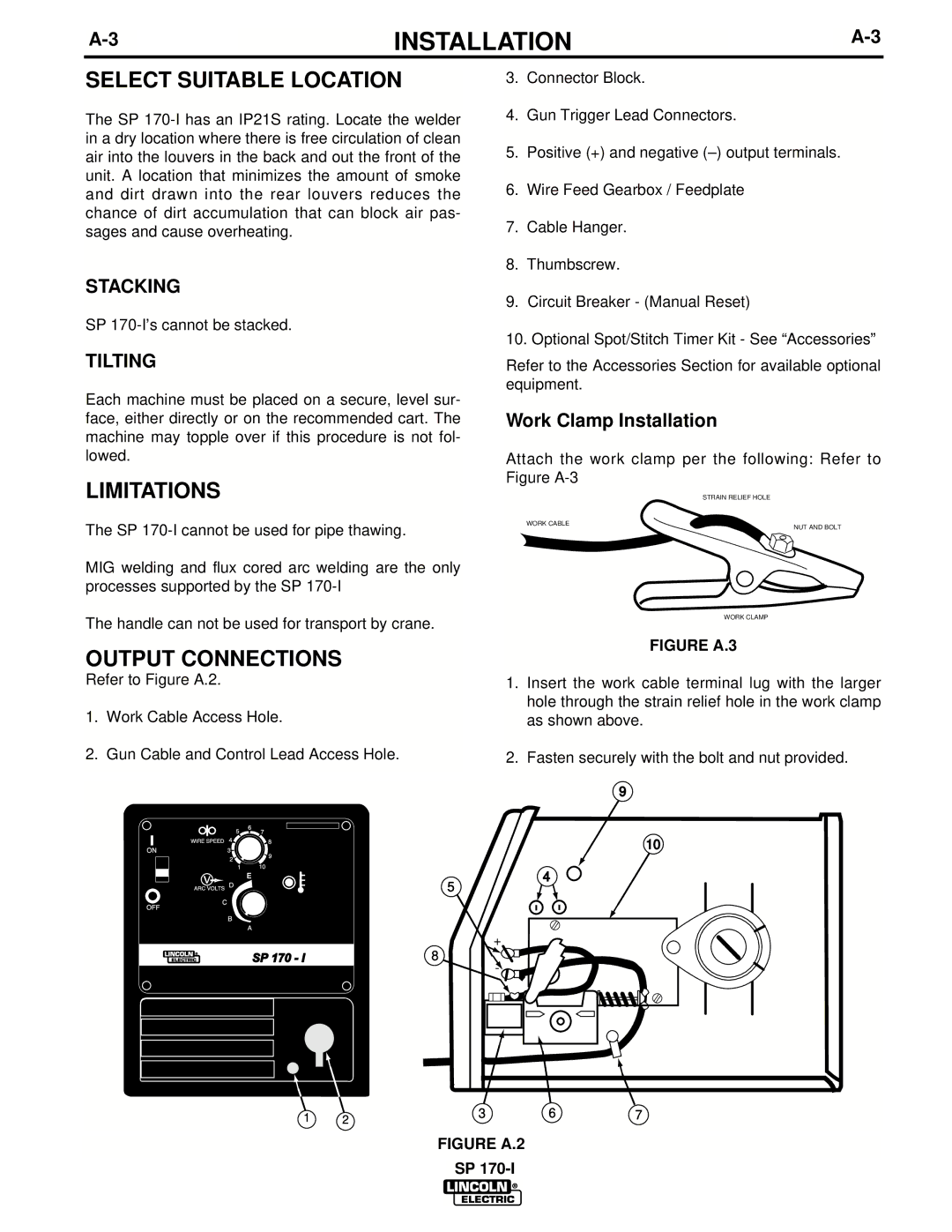
OUTPUT CONNECTIONS
Refer to Figure A.2.
1.Work Cable Access Hole.
2.Gun Cable and Control Lead Access Hole.
E
5
SP 170 - I | 8 |
3.Connector Block.
4.Gun Trigger Lead Connectors.
5.Positive (+) and negative
6.Wire Feed Gearbox / Feedplate
7.Cable Hanger.
8.Thumbscrew.
9.Circuit Breaker - (Manual Reset)
10.Optional Spot/Stitch Timer Kit - See “Accessories”
Refer to the Accessories Section for available optional equipment.
Work Clamp Installation
Attach the work clamp per the following: Refer to Figure
STRAIN RELIEF HOLE
WORK CABLE
NUT AND BOLT
WORK CLAMP
FIGURE A.3
1.Insert the work cable terminal lug with the larger hole through the strain relief hole in the work clamp as shown above.
2.Fasten securely with the bolt and nut provided.
9
10
4
+
-
1 | 2 | 3 | 6 | 7 |
FIGURE A.2
SP