|
| OPERATION |
| ||
|
|
|
|
|
|
WELDING OPERATIONS
SEQUENCE OF OPERATION
Wire Loading
Refer to Figures B.2 and B.3.
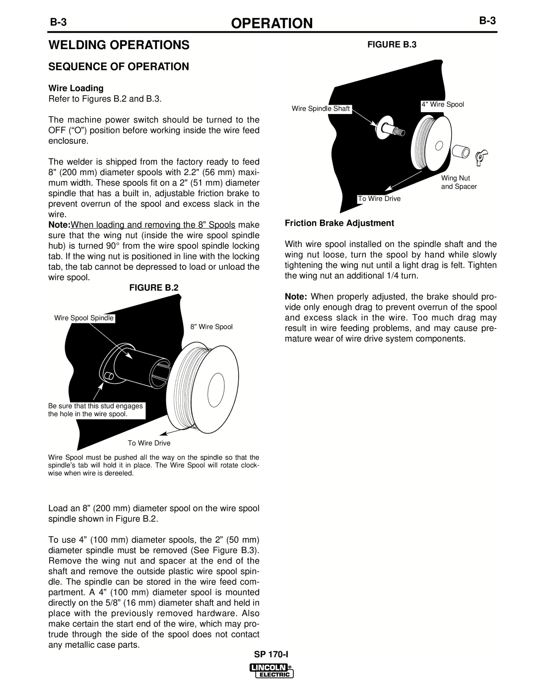
FIGURE B.3
The machine power switch should be turned to the OFF (“O”) position before working inside the wire feed enclosure.
The welder is shipped from the factory ready to feed 8" (200 mm) diameter spools with 2.2" (56 mm) maxi- mum width. These spools fit on a 2" (51 mm) diameter spindle that has a built in, adjustable friction brake to
Wire Spindle Shaft
4" Wire Spool
Wing Nut
and Spacer
prevent overrun of the spool and excess slack in the wire.
Note:When loading and removing the 8” Spools make sure that the wing nut (inside the wire spool spindle hub) is turned 90° from the wire spool spindle locking tab. If the wing nut is positioned in line with the locking tab, the tab cannot be depressed to load or unload the wire spool.
FIGURE B.2
Wire Spool Spindle
8” Wire Spool
Be sure that this stud engages the hole in the wire spool.
To Wire Drive
Wire Spool must be pushed all the way on the spindle so that the spindle’s tab will hold it in place. The Wire Spool will rotate clock- wise when wire is dereeled.
To Wire Drive
Friction Brake Adjustment
With wire spool installed on the spindle shaft and the wing nut loose, turn the spool by hand while slowly tightening the wing nut until a light drag is felt. Tighten the wing nut an additional 1/4 turn.
Note: When properly adjusted, the brake should pro- vide only enough drag to prevent overrun of the spool and excess slack in the wire. Too much drag may result in wire feeding problems, and may cause pre- mature wear of wire drive system components.
Load an 8” (200 mm) diameter spool on the wire spool spindle shown in Figure B.2.
To use 4” (100 mm) diameter spools, the 2” (50 mm) diameter spindle must be removed (See Figure B.3). Remove the wing nut and spacer at the end of the shaft and remove the outside plastic wire spool spin- dle. The spindle can be stored in the wire feed com- partment. A 4” (100 mm) diameter spool is mounted directly on the 5/8” (16 mm) diameter shaft and held in place with the previously removed hardware. Also make certain the start end of the wire, which may pro- trude through the side of the spool does not contact any metallic case parts.
SP