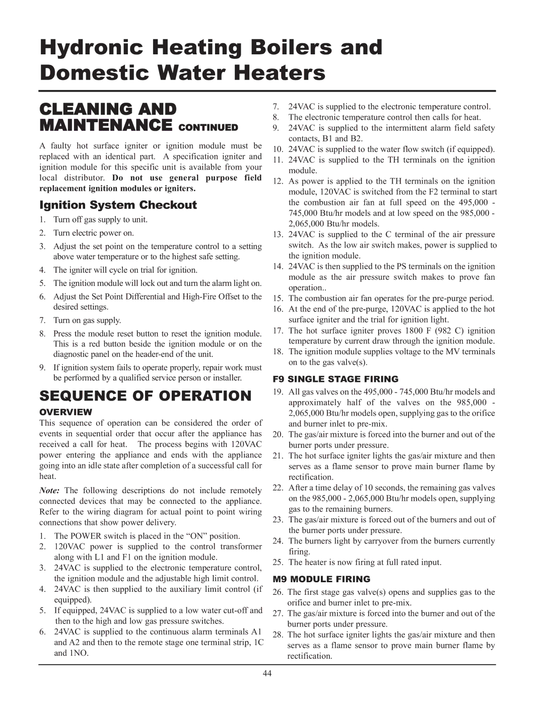
000 - 2, 065, 495 specifications
Lochinvar 000 - 2,495,065 is a cutting-edge water heating solution designed to meet the needs of modern residential and commercial applications. This high-efficiency unit combines advanced engineering with robust technologies, providing unmatched performance and reliability.One of the standout features of the Lochinvar 000 - 2,495,065 is its high thermal efficiency, which often exceeds 95%. Utilizing condensing technology, the unit harnesses heat from exhaust gases, allowing it to recover otherwise lost energy, thereby reducing operational costs significantly. This efficiency not only lowers energy bills for users but also lessens the environmental impact by minimizing greenhouse gas emissions.
The Lochinvar 000 - 2,495,065 is equipped with a lightweight stainless steel heat exchanger. This construction ensures exceptional corrosion resistance and longevity, extending the lifespan of the unit while maintaining optimal performance. The stainless steel design also contributes to faster heating times, making it ideal for high-demand environments.
In terms of control technologies, the Lochinvar 000 - 2,495,065 features an intuitive touchscreen interface. This user-friendly design allows for seamless operation, real-time monitoring, and easy adjustments to temperature settings. Additionally, it facilitates remote diagnostics, promoting efficient maintenance and reducing downtime, which is crucial for busy facilities.
For enhanced safety, the Lochinvar 000 - 2,495,065 includes multiple safety mechanisms, such as over-temperature protection, flame safeguard, and leak detection systems. These safety features ensure secure operation and give users peace of mind.
Moreover, the unit is compatible with various fuel sources, including natural gas and propane, making it versatile and adaptable to different infrastructure requirements. This flexibility ensures that the Lochinvar 000 - 2,495,065 can be integrated into various settings, from residential homes to large commercial buildings.
Another significant characteristic is its compact design, allowing for easy installation in tight spaces. The footprint of the Lochinvar 000 - 2,495,065 makes it an ideal solution for applications where space is at a premium, without compromising on performance.
In summary, Lochinvar 000 - 2,495,065 represents a premium choice for water heating solutions, merging advanced technologies, high efficiency, and user-friendly design to cater to a wide range of heating needs while ensuring safety and sustainability.

