Hydronic Heating Boilers and Domestic Water Heaters

INSTALLATION

Continued

TABLE - J

Nominal AMP Draw Data

TABLE

AMP Draw Data


Btu/Hr


Approximate

Input

Controls

Fan

Total Amps


495,000

4.6

3.4


8.0

645,000

4.6

3.4


8.0

745,000

4.6

3.4


8.0

985,000

4.6

3.4


8.0

1,255,000

4.6

3.4


8.0

1,435,000

4.6

3.8


8.4


1,795,000

4.6

3.8


8.4


2,065,000

4.6

3.8


8.4


IMPORTANT: Do not block access to the electrical cover plate when installing electrical conduit.

External EMS Connection to Terminal Strip for Stage Firing Control of Burners

This unit is equipped with a factory installed terminal strip for connection of an energy management system (EMS) to the burner stages. The EMS terminal strip is located in the unit's junction box. Ensure that all wiring used for connection to this terminal strip is properly sized per the recommendations in TABLE-L. When connecting an EMS to this terminal strip to sequence on each stage of burner operation, the unit's internal thermostat or electronic sequencer should be set as an additional high limit control. This will prevent problems between the set points of the EMS and the boiler's internal controller.

Terminal Strip Connection Options

(Models 985,000 - 2,065,000 Btu/hr Only)

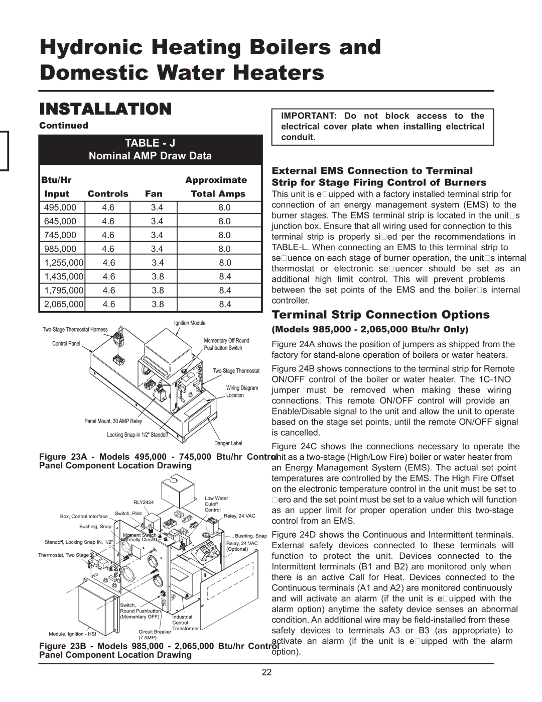
Figure 23A - Models 495,000 - 745,000 Btu/hr Control Panel Component Location Drawing

Figure 23B - Models 985,000 - 2,065,000 Btu/hr Control Panel Component Location Drawing

Figure 24A shows the position of jumpers as shipped from the factory for stand-alone operation of boilers or water heaters.

Figure 24B shows connections to the terminal strip for Remote ON/OFF control of the boiler or water heater. The 1C-1NO jumper must be removed when making these wiring connections. This remote ON/OFF control will provide an Enable/Disable signal to the unit and allow the unit to operate based on the stage set points, until the remote ON/OFF signal is cancelled.

Figure 24C shows the connections necessary to operate the unit as a two-stage (High/Low Fire) boiler or water heater from an Energy Management System (EMS). The actual set point temperatures are controlled by the EMS. The High Fire Offset on the electronic temperature control in the unit must be set to zero and the set point must be set to a value which will function as an upper limit for proper operation under this two-stage control from an EMS.

Figure 24D shows the Continuous and Intermittent terminals. External safety devices connected to these terminals will function to protect the unit. Devices connected to the Intermittent terminals (B1 and B2) are monitored only when there is an active Call for Heat. Devices connected to the Continuous terminals (A1 and A2) are monitored continuously and will activate an alarm (if the unit is equipped with the alarm option) anytime the safety device senses an abnormal condition. An additional wire may be field-installed from these safety devices to terminals A3 or B3 (as appropriate) to activate an alarm (if the unit is equipped with the alarm option).

22

Page 22
Image 22
Lochinvar 065, 495, 000 - 2 service manual Terminal Strip Connection Options, Table J, Nominal AMP Draw Data

000 - 2, 065, 495 specifications

Lochinvar 000 - 2,495,065 is a cutting-edge water heating solution designed to meet the needs of modern residential and commercial applications. This high-efficiency unit combines advanced engineering with robust technologies, providing unmatched performance and reliability.

One of the standout features of the Lochinvar 000 - 2,495,065 is its high thermal efficiency, which often exceeds 95%. Utilizing condensing technology, the unit harnesses heat from exhaust gases, allowing it to recover otherwise lost energy, thereby reducing operational costs significantly. This efficiency not only lowers energy bills for users but also lessens the environmental impact by minimizing greenhouse gas emissions.

The Lochinvar 000 - 2,495,065 is equipped with a lightweight stainless steel heat exchanger. This construction ensures exceptional corrosion resistance and longevity, extending the lifespan of the unit while maintaining optimal performance. The stainless steel design also contributes to faster heating times, making it ideal for high-demand environments.

In terms of control technologies, the Lochinvar 000 - 2,495,065 features an intuitive touchscreen interface. This user-friendly design allows for seamless operation, real-time monitoring, and easy adjustments to temperature settings. Additionally, it facilitates remote diagnostics, promoting efficient maintenance and reducing downtime, which is crucial for busy facilities.

For enhanced safety, the Lochinvar 000 - 2,495,065 includes multiple safety mechanisms, such as over-temperature protection, flame safeguard, and leak detection systems. These safety features ensure secure operation and give users peace of mind.

Moreover, the unit is compatible with various fuel sources, including natural gas and propane, making it versatile and adaptable to different infrastructure requirements. This flexibility ensures that the Lochinvar 000 - 2,495,065 can be integrated into various settings, from residential homes to large commercial buildings.

Another significant characteristic is its compact design, allowing for easy installation in tight spaces. The footprint of the Lochinvar 000 - 2,495,065 makes it an ideal solution for applications where space is at a premium, without compromising on performance.

In summary, Lochinvar 000 - 2,495,065 represents a premium choice for water heating solutions, merging advanced technologies, high efficiency, and user-friendly design to cater to a wide range of heating needs while ensuring safety and sustainability.