Installation and Service Manual

9.If gas pressure is out of range, contact your gas utility, gas supplier, qualified installer or service agency to determine the necessary steps to provide proper gas pressure to the control.

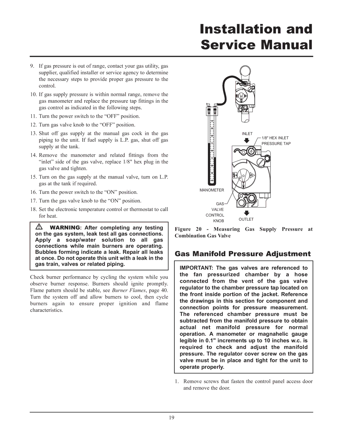
10.If gas supply pressure is within normal range, remove the gas manometer and replace the pressure tap fittings in the gas control as indicated in the following steps.

11.Turn the power switch to the “OFF” position.

12.Turn gas valve knob to the “OFF” position.

13.Shut off gas supply at the manual gas cock in the gas piping to the unit. If fuel supply is L.P. gas, shut off gas supply at the tank.

14.Remove the manometer and related fittings from the “inlet” side of the gas valve, replace 1/8" hex plug in the gas valve and tighten.

15.Turn on the gas supply at the manual valve, turn on L.P. gas at the tank if required.

16.Turn the power switch to the “ON” position.

17.Turn the gas valve knob to the “ON” position.

18.Set the electronic temperature control or thermostat to call for heat.

￿WARNING: After completing any testing on the gas system, leak test all gas connections. Apply a soap/water solution to all gas connections while main burners are operating. Bubbles forming indicate a leak. Repair all leaks at once. Do not operate this unit with a leak in the gas train, valves or related piping.

Check burner performance by cycling the system while you observe burner response. Burners should ignite promptly. Flame pattern should be stable, see Burner Flames, page 40. Turn the system off and allow burners to cool, then cycle burners again to ensure proper ignition and flame characteristics.

4


3


2

INLET

1/8" HEX INLET


1

PRESSURE TAP

0


1


2


3


4


MANOMETER


GAS

VALVE

CONTROL

KNOB OUTLET

Figure 20 - Measuring Gas Supply Pressure at Combination Gas Valve

Gas Manifold Pressure Adjustment

IMPORTANT: The gas valves are referenced to the fan pressurized chamber by a hose connected from the vent of the gas valve regulator to the chamber pressure tap located on the front inside portion of the jacket. Reference the drawings in this section for component and connection points for pressure measurement. The referenced chamber pressure must be subtracted from the manifold pressure to obtain actual net manifold pressure for normal operation. A manometer or magnahelic gauge legible in 0.1" increments up to 10 inches w.c. is required to check and adjust the manifold pressure. The regulator cover screw on the gas valve must be in place and tight for the unit to operate properly.

1.Remove screws that fasten the control panel access door and remove the door.

19

Page 19
Image 19
Lochinvar 065, 495, 000 - 2 Gas Manifold Pressure Adjustment, Measuring Gas Supply Pressure at Combination Gas Valve

000 - 2, 065, 495 specifications

Lochinvar 000 - 2,495,065 is a cutting-edge water heating solution designed to meet the needs of modern residential and commercial applications. This high-efficiency unit combines advanced engineering with robust technologies, providing unmatched performance and reliability.

One of the standout features of the Lochinvar 000 - 2,495,065 is its high thermal efficiency, which often exceeds 95%. Utilizing condensing technology, the unit harnesses heat from exhaust gases, allowing it to recover otherwise lost energy, thereby reducing operational costs significantly. This efficiency not only lowers energy bills for users but also lessens the environmental impact by minimizing greenhouse gas emissions.

The Lochinvar 000 - 2,495,065 is equipped with a lightweight stainless steel heat exchanger. This construction ensures exceptional corrosion resistance and longevity, extending the lifespan of the unit while maintaining optimal performance. The stainless steel design also contributes to faster heating times, making it ideal for high-demand environments.

In terms of control technologies, the Lochinvar 000 - 2,495,065 features an intuitive touchscreen interface. This user-friendly design allows for seamless operation, real-time monitoring, and easy adjustments to temperature settings. Additionally, it facilitates remote diagnostics, promoting efficient maintenance and reducing downtime, which is crucial for busy facilities.

For enhanced safety, the Lochinvar 000 - 2,495,065 includes multiple safety mechanisms, such as over-temperature protection, flame safeguard, and leak detection systems. These safety features ensure secure operation and give users peace of mind.

Moreover, the unit is compatible with various fuel sources, including natural gas and propane, making it versatile and adaptable to different infrastructure requirements. This flexibility ensures that the Lochinvar 000 - 2,495,065 can be integrated into various settings, from residential homes to large commercial buildings.

Another significant characteristic is its compact design, allowing for easy installation in tight spaces. The footprint of the Lochinvar 000 - 2,495,065 makes it an ideal solution for applications where space is at a premium, without compromising on performance.

In summary, Lochinvar 000 - 2,495,065 represents a premium choice for water heating solutions, merging advanced technologies, high efficiency, and user-friendly design to cater to a wide range of heating needs while ensuring safety and sustainability.