Hydronic Heating Boilers and Domestic Water Heaters

INSTALLATION

Continued

Sludge formed as the result of excessive oxygen in the system can restrict water flow resulting in a premature boiler failure. Any boiler damage due to excessive oxygenation is non- warrantable.

Installation with a Chilled Water System

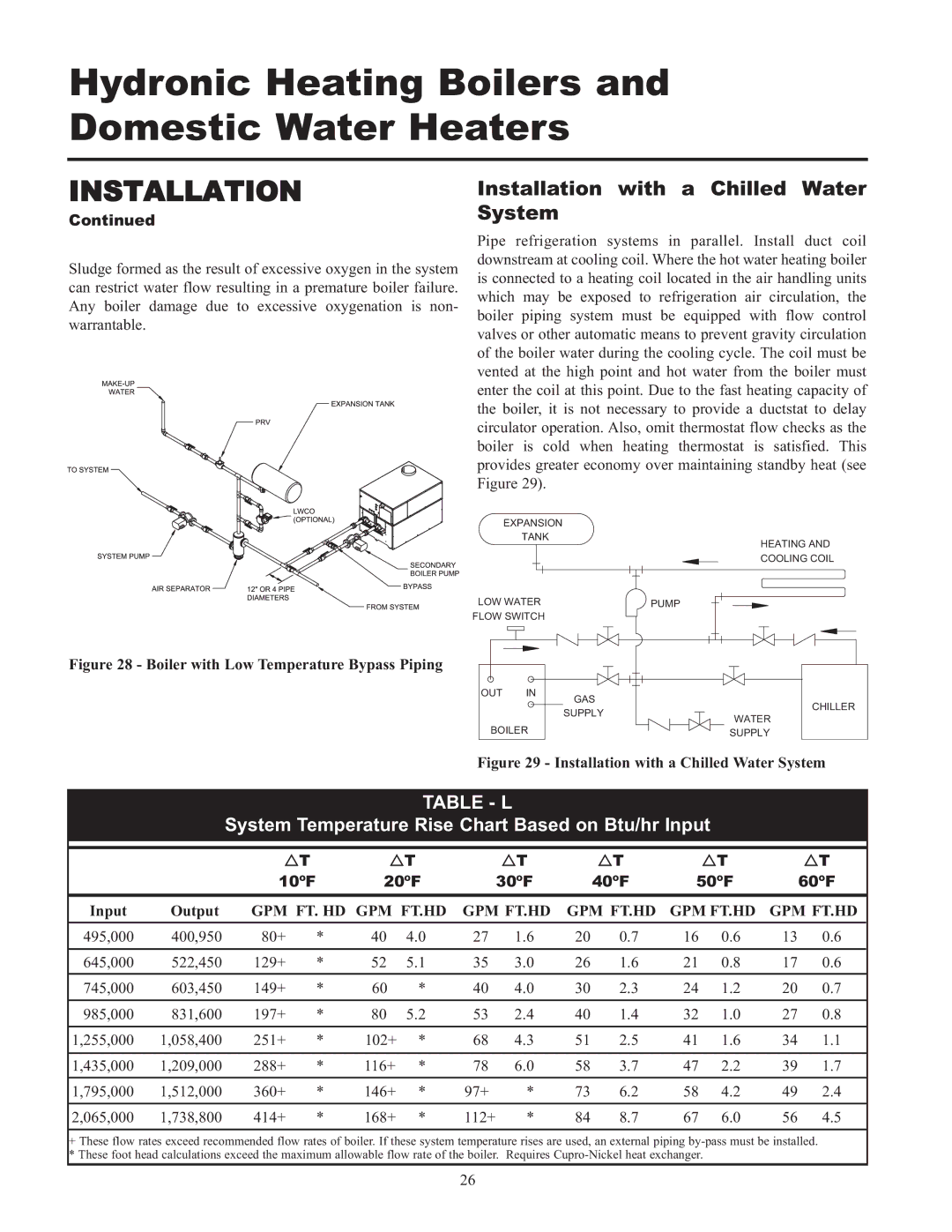
Pipe refrigeration systems in parallel. Install duct coil downstream at cooling coil. Where the hot water heating boiler is connected to a heating coil located in the air handling units which may be exposed to refrigeration air circulation, the boiler piping system must be equipped with flow control valves or other automatic means to prevent gravity circulation of the boiler water during the cooling cycle. The coil must be vented at the high point and hot water from the boiler must enter the coil at this point. Due to the fast heating capacity of the boiler, it is not necessary to provide a ductstat to delay circulator operation. Also, omit thermostat flow checks as the boiler is cold when heating thermostat is satisfied. This provides greater economy over maintaining standby heat (see Figure 29).

EXPANSION

TANK

HEATING AND

COOLING COIL

LOW WATER


PUMP


FLOW SWITCH


Figure 28 - Boiler with Low Temperature Bypass Piping

OUT IN

BOILER

GAS

SUPPLY

WATER SUPPLY

CHILLER

Figure 29 - Installation with a Chilled Water System

TABLE - L

System Temperature Rise Chart Based on Btu/hr Input


System Temperature Risased on Btu/hr Input


￿T


￿T


￿T


￿T


￿T


￿T


10ºF


20ºF


30ºF


40ºF

50ºF


60ºF


Input

Output

GPM FT. HD GPM FT.HD

GPM FT.HD

GPM FT.HD

GPM FT.HD

GPM FT.HD


495,000

400,950

80+

*

40

4.0

27

1.6

20

0.7

16

0.6

13

0.6


645,000

522,450

129+

*

52

5.1

35

3.0

26

1.6

21

0.8

17

0.6


745,000

603,450

149+

*

60

*

40

4.0

30

2.3

24

1.2

20

0.7


985,000

831,600

197+

*

80

5.2

53

2.4

40

1.4

32

1.0

27

0.8


1,255,000

1,058,400

251+

*

102+

*

68

4.3

51

2.5

41

1.6

34

1.1


1,435,000

1,209,000

288+

*

116+

*

78

6.0

58

3.7

47

2.2

39

1.7


1,795,000

1,512,000

360+

*

146+

*

97+

*

73

6.2

58

4.2

49

2.4


2,065,000

1,738,800

414+

*

168+

*

112+

*

84

8.7

67

6.0

56

4.5


+These flow rates exceed recommended flow rates of boiler. If these system temperature rises are used, an external piping by-pass must be installed. * These foot head calculations exceed the maximum allowable flow rate of the boiler. Requires Cupro-Nickel heat exchanger.

26

Page 26
Image 26
Lochinvar 000 - 2 Installation with a Chilled Water System, Table L, System Temperature Rise Chart Based on Btu/hr Input

000 - 2, 065, 495 specifications

Lochinvar 000 - 2,495,065 is a cutting-edge water heating solution designed to meet the needs of modern residential and commercial applications. This high-efficiency unit combines advanced engineering with robust technologies, providing unmatched performance and reliability.

One of the standout features of the Lochinvar 000 - 2,495,065 is its high thermal efficiency, which often exceeds 95%. Utilizing condensing technology, the unit harnesses heat from exhaust gases, allowing it to recover otherwise lost energy, thereby reducing operational costs significantly. This efficiency not only lowers energy bills for users but also lessens the environmental impact by minimizing greenhouse gas emissions.

The Lochinvar 000 - 2,495,065 is equipped with a lightweight stainless steel heat exchanger. This construction ensures exceptional corrosion resistance and longevity, extending the lifespan of the unit while maintaining optimal performance. The stainless steel design also contributes to faster heating times, making it ideal for high-demand environments.

In terms of control technologies, the Lochinvar 000 - 2,495,065 features an intuitive touchscreen interface. This user-friendly design allows for seamless operation, real-time monitoring, and easy adjustments to temperature settings. Additionally, it facilitates remote diagnostics, promoting efficient maintenance and reducing downtime, which is crucial for busy facilities.

For enhanced safety, the Lochinvar 000 - 2,495,065 includes multiple safety mechanisms, such as over-temperature protection, flame safeguard, and leak detection systems. These safety features ensure secure operation and give users peace of mind.

Moreover, the unit is compatible with various fuel sources, including natural gas and propane, making it versatile and adaptable to different infrastructure requirements. This flexibility ensures that the Lochinvar 000 - 2,495,065 can be integrated into various settings, from residential homes to large commercial buildings.

Another significant characteristic is its compact design, allowing for easy installation in tight spaces. The footprint of the Lochinvar 000 - 2,495,065 makes it an ideal solution for applications where space is at a premium, without compromising on performance.

In summary, Lochinvar 000 - 2,495,065 represents a premium choice for water heating solutions, merging advanced technologies, high efficiency, and user-friendly design to cater to a wide range of heating needs while ensuring safety and sustainability.