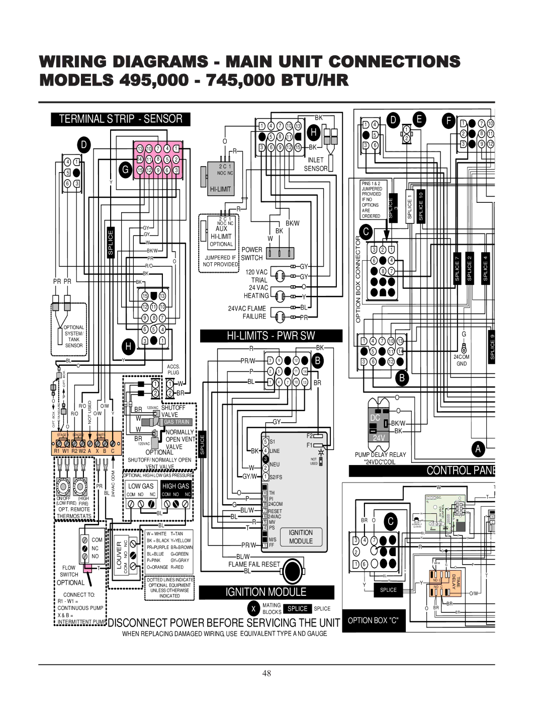
WIRING DIAGRAMS - MAIN UNIT CONNECTIONS MODELS 495,000 - 745,000 BTU/HR


TERMINAL STRIP

- SENSOR


BK


D


E


F


1


1

4

7

10

13


1

4


7


10


H


1


2

8


11


5

8

11


5


2


O


D


BK


3

6


3

9


12


13

10

7

4


1


3

6

9

12

15


R


4

1


14

11

8

5


2


INLET


2 C 1


G

15

12

9

6


3


SENSOR


5


NOC

NC


6

3


Y


PINS 1 & 2


HI-LIMIT


JUMPERED


PROVIDED


10ICE SPL


1SPLICE


IF NO


ICE 3 SPL


R


OPTIONS


ARE


2 C 1


ORDERED


BK/W


GY


NOC NC


ICESPL


AUX


BK


C


GY


HI-LIMIT


CONNECTORBOX


W


W


OPTIONAL


POWER


BK/W


3

2

1


PR


O


JUMPERED IF

SWITCH


6


4


7SPLICE


2SPLICE

4SPLICE


NOT PROVIDED


R/O


GY


120 VAC


8

7


BK


GY


PR PR


BK


TRIAL


24 VAC


O


15


13


HEATING


Y


OPTION


12

11


10


24VAC FLAME


BL


9


8


7


FAILURE


PR


OPTIONAL


6


5


4


SYSTEM/


HI-LIMITS - PWR SW


G


9


TANK


3


1


1

4

7

10

13


ICE


SENSOR


H


R


BK


5


11

14


SPL


BL


Y


PR/W


3

6


12


B


3

6


12


24COM


GND


O


ACCS.


.


P


2

5


11

14


BOX.


PLUG


B


BL


TP


1


1

W


1

4

7

10

13

BR


O


P


2


2

BR


O


O


USEDNOT


R/O

O/W

BR

120VAC

SHUTOFF


O


R/O


O/W

Y


VALVE


.BOX .TP

RDADNSTA


W


DC


GAS TRAIN


GY


BK/W


O

O


W


BK


NORMALLY


STAGE 1

STAGE 2


LIMITS


SPLICE


F2


24V


BR


OPEN VENT


5

S1


120VAC


VALVE


F1


A


BK

4


R1 W1 R2 W2 A

X B

C


LINE


OPTIONAL


PUMP DELAY RELAY


SHUTOFF/ NORMALLY OPEN


3


NOT


"24VDC"COIL


VENT VALVE


W

2

NEU


USED


CONTROL PANE


COM


OPTIONAL HIGH-LOW GAS PRESSURE


GY/W

1

S2/FS


PR


LOW GAS


HIGH GAS


W


T


BL 24VAC


(HIGH

COM NO


NC


COM NO

NC


O

10

TH


O.C.


T


ON/OFF


P

9

PI


J1


(LOW FIRE)

FIRE)


J3


G


8

24COM


L


6

3


OPT. REMOTE


BL/W


CVA OR 24 TCON

O


5 4

2


7

RESET


BL


1

PR


PR


THERMOSTATS


BL

6

24VAC


T

NO


C


P


BR

O


R

5

MV


PR


J2


RESET


1

2

3


C


BL


NORMALLY


J4


T

4

PS


CLOSED


P


GND


IGNITION


GND


W = WHITE

T=TAN


3


BL


P


PR


2


Y


O


Y


Y


COM

LOUVER

NC NO COM


BK = BLACK Y=YELLOW


M/S

MODULE

3

4

7


G


PR/W


1

FF


NC


PR=PURPLE BR=BROWN


R


2

5

8


G


BL=BLUE

G=GREEN


NO


BL/W


P=PINK

GY=GRAY


FLAME FAIL RESET


1

6

9


T

BR/W


G


P


FLOW


T


O=ORANGE R=RED


O


BL


Y


SWITCH


BL


DELAY


T


TIME


DOTTED LINES INDICATE


OPTIONAL


Y


Y


NO C


OPTIONAL EQUIPMENT


Y


NO

C


IGNITION MODULE


SPLICE


UNLESS OTHERWISE


CONNECT TO:


O/W


INDICATED


R1 - W1 =


x

MATING


BR


CONTINUOUS PUMP


SPLICE


O

BR


SPLICE


BLOCKS


BR


X & B =


OPTION BOX "C"


INTERMITTENT PUMP

DISCONNECT POWER BEFORE SERVICING THE UNIT


WHEN REPLACING DAMAGED WIRING, USE EQUIVALENT TYPE AND GAUGE.


48


Page 48
Image 48
Lochinvar 495, 065, 000 - 2 service manual Hi-Limits Pwr Sw

000 - 2, 065, 495 specifications

Lochinvar 000 - 2,495,065 is a cutting-edge water heating solution designed to meet the needs of modern residential and commercial applications. This high-efficiency unit combines advanced engineering with robust technologies, providing unmatched performance and reliability.

One of the standout features of the Lochinvar 000 - 2,495,065 is its high thermal efficiency, which often exceeds 95%. Utilizing condensing technology, the unit harnesses heat from exhaust gases, allowing it to recover otherwise lost energy, thereby reducing operational costs significantly. This efficiency not only lowers energy bills for users but also lessens the environmental impact by minimizing greenhouse gas emissions.

The Lochinvar 000 - 2,495,065 is equipped with a lightweight stainless steel heat exchanger. This construction ensures exceptional corrosion resistance and longevity, extending the lifespan of the unit while maintaining optimal performance. The stainless steel design also contributes to faster heating times, making it ideal for high-demand environments.

In terms of control technologies, the Lochinvar 000 - 2,495,065 features an intuitive touchscreen interface. This user-friendly design allows for seamless operation, real-time monitoring, and easy adjustments to temperature settings. Additionally, it facilitates remote diagnostics, promoting efficient maintenance and reducing downtime, which is crucial for busy facilities.

For enhanced safety, the Lochinvar 000 - 2,495,065 includes multiple safety mechanisms, such as over-temperature protection, flame safeguard, and leak detection systems. These safety features ensure secure operation and give users peace of mind.

Moreover, the unit is compatible with various fuel sources, including natural gas and propane, making it versatile and adaptable to different infrastructure requirements. This flexibility ensures that the Lochinvar 000 - 2,495,065 can be integrated into various settings, from residential homes to large commercial buildings.

Another significant characteristic is its compact design, allowing for easy installation in tight spaces. The footprint of the Lochinvar 000 - 2,495,065 makes it an ideal solution for applications where space is at a premium, without compromising on performance.

In summary, Lochinvar 000 - 2,495,065 represents a premium choice for water heating solutions, merging advanced technologies, high efficiency, and user-friendly design to cater to a wide range of heating needs while ensuring safety and sustainability.