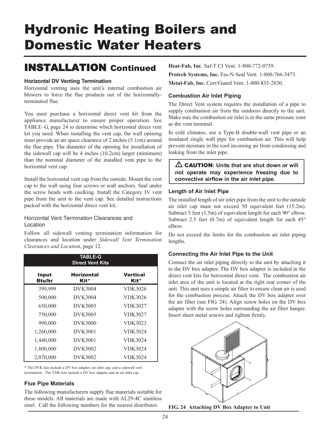
399, CF-CH(E)-i&s-08, 999 - 750 specifications
Lochinvar 999 - 750, CF-CH(E)-i&s-08,399 is a cutting-edge boiler designed for commercial heating applications. With its robust construction and high efficiency, this model stands out in the crowded market of heating solutions.One of the main features of the Lochinvar 999 - 750 is its exceptional thermal efficiency rating. The unit incorporates advanced condensing technology that allows it to recover heat from flue gases, which helps in achieving efficiency levels of up to 99%. This efficiency not only reduces energy consumption but also lowers operational costs, making it an excellent investment for businesses looking to minimize their carbon footprint.
The boiler is designed to provide a powerful output of 750 kW, ensuring it meets the heating demands of larger buildings or commercial spaces. Its capacity makes it suitable for a range of applications including schools, hospitals, and industrial facilities. Moreover, the unit features a built-in cascading system that enables multiple boilers to be connected, enhancing system reliability and flexibility.
In terms of technology, the Lochinvar 999 - 750 is equipped with a user-friendly touchscreen interface. This innovative control system allows operators to monitor and adjust settings with ease, providing real-time performance data and alerts for maintenance needs. The intelligent controls optimize operation to match the heating load, further enhancing energy efficiency.
Safety is a top priority with this model. It is built with multiple safety features such as automatic shut-off valves, pressure relief valves, and flame monitoring systems, ensuring safe operation under various conditions. The unit also adheres to stringent industry standards and regulations, making it a reliable choice for commercial applications.
Furthermore, the Lochinvar 999 - 750 is designed with serviceability in mind. Its compact footprint and accessible components simplify maintenance, reducing downtime and associated costs. The unit also supports a variety of fuel sources, including natural gas, propane, and biodiesel, providing flexibility to meet different facility requirements.
In summary, the Lochinvar 999 - 750, CF-CH(E)-i&s-08,399 represents a blend of efficiency, reliability, and safety in commercial heating. Its advanced technologies and thoughtful design make it a powerful solution for various heating needs, making it an ideal choice for businesses aiming for excellence in energy management and operational efficiency.

