Installation and Service Manual

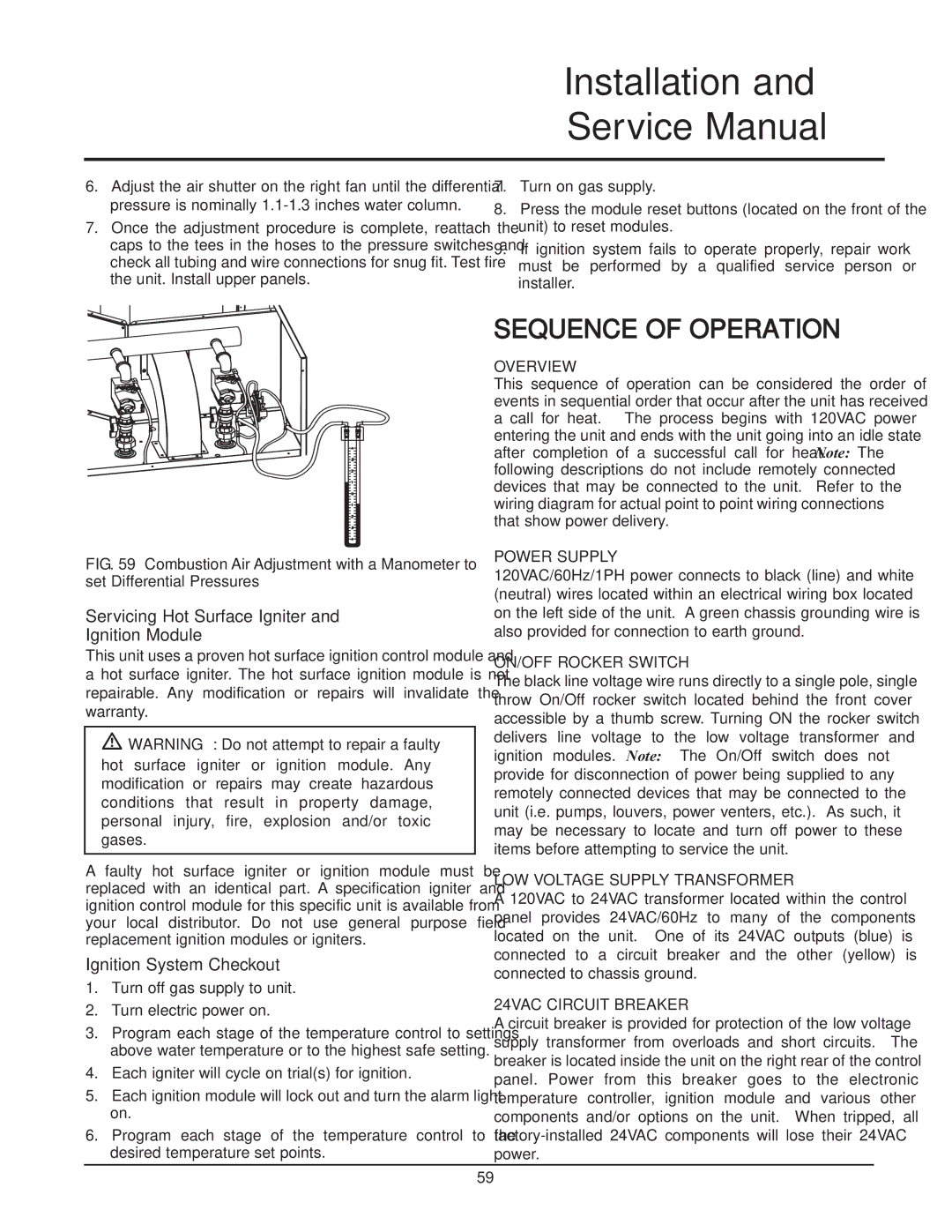
6.Adjust the air shutter on the right fan until the differential pressure is nominally 1.1-1.3 inches water column.

7.Once the adjustment procedure is complete, reattach the caps to the tees in the hoses to the pressure switches and check all tubing and wire connections for snug fit. Test fire the unit. Install upper panels.

7.Turn on gas supply.

8.Press the module reset buttons (located on the front of the unit) to reset modules.

9.If ignition system fails to operate properly, repair work must be performed by a qualified service person or installer.

FIG. 59 Combustion Air Adjustment with a Manometer to set Differential Pressures

Servicing Hot Surface Igniter and Ignition Module

This unit uses a proven hot surface ignition control module and a hot surface igniter. The hot surface ignition module is not repairable. Any modification or repairs will invalidate the warranty.

WARNING: Do not attempt to repair a faulty hot surface igniter or ignition module. Any modification or repairs may create hazardous conditions that result in property damage, personal injury, fire, explosion and/or toxic gases.

A faulty hot surface igniter or ignition module must be replaced with an identical part. A specification igniter and ignition control module for this specific unit is available from your local distributor. Do not use general purpose field replacement ignition modules or igniters.

Ignition System Checkout

1.Turn off gas supply to unit.

2.Turn electric power on.

3.Program each stage of the temperature control to settings above water temperature or to the highest safe setting.

4.Each igniter will cycle on trial(s) for ignition.

5.Each ignition module will lock out and turn the alarm light on.

6.Program each stage of the temperature control to the desired temperature set points.

SEQUENCE OF OPERATION

OVERVIEW

This sequence of operation can be considered the order of events in sequential order that occur after the unit has received a call for heat. The process begins with 120VAC power entering the unit and ends with the unit going into an idle state after completion of a successful call for heat. Note: The following descriptions do not include remotely connected devices that may be connected to the unit. Refer to the wiring diagram for actual point to point wiring connections that show power delivery.

POWER SUPPLY

120VAC/60Hz/1PH power connects to black (line) and white (neutral) wires located within an electrical wiring box located on the left side of the unit. A green chassis grounding wire is also provided for connection to earth ground.

ON/OFF ROCKER SWITCH

The black line voltage wire runs directly to a single pole, single throw On/Off rocker switch located behind the front cover accessible by a thumb screw. Turning ON the rocker switch delivers line voltage to the low voltage transformer and ignition modules. Note: The On/Off switch does not provide for disconnection of power being supplied to any remotely connected devices that may be connected to the unit (i.e. pumps, louvers, power venters, etc.). As such, it may be necessary to locate and turn off power to these items before attempting to service the unit.

LOW VOLTAGE SUPPLY TRANSFORMER

A 120VAC to 24VAC transformer located within the control panel provides 24VAC/60Hz to many of the components located on the unit. One of its 24VAC outputs (blue) is connected to a circuit breaker and the other (yellow) is connected to chassis ground.

24VAC CIRCUIT BREAKER

A circuit breaker is provided for protection of the low voltage supply transformer from overloads and short circuits. The breaker is located inside the unit on the right rear of the control panel. Power from this breaker goes to the electronic temperature controller, ignition module and various other components and/or options on the unit. When tripped, all factory-installed 24VAC components will lose their 24VAC power.

59

Page 59
Image 59
Lochinvar 399, 999 - 750, CF-CH(E)-i&s-08 Servicing Hot Surface Igniter and Ignition Module, Ignition System Checkout

399, CF-CH(E)-i&s-08, 999 - 750 specifications

Lochinvar 999 - 750, CF-CH(E)-i&s-08,399 is a cutting-edge boiler designed for commercial heating applications. With its robust construction and high efficiency, this model stands out in the crowded market of heating solutions.

One of the main features of the Lochinvar 999 - 750 is its exceptional thermal efficiency rating. The unit incorporates advanced condensing technology that allows it to recover heat from flue gases, which helps in achieving efficiency levels of up to 99%. This efficiency not only reduces energy consumption but also lowers operational costs, making it an excellent investment for businesses looking to minimize their carbon footprint.

The boiler is designed to provide a powerful output of 750 kW, ensuring it meets the heating demands of larger buildings or commercial spaces. Its capacity makes it suitable for a range of applications including schools, hospitals, and industrial facilities. Moreover, the unit features a built-in cascading system that enables multiple boilers to be connected, enhancing system reliability and flexibility.

In terms of technology, the Lochinvar 999 - 750 is equipped with a user-friendly touchscreen interface. This innovative control system allows operators to monitor and adjust settings with ease, providing real-time performance data and alerts for maintenance needs. The intelligent controls optimize operation to match the heating load, further enhancing energy efficiency.

Safety is a top priority with this model. It is built with multiple safety features such as automatic shut-off valves, pressure relief valves, and flame monitoring systems, ensuring safe operation under various conditions. The unit also adheres to stringent industry standards and regulations, making it a reliable choice for commercial applications.

Furthermore, the Lochinvar 999 - 750 is designed with serviceability in mind. Its compact footprint and accessible components simplify maintenance, reducing downtime and associated costs. The unit also supports a variety of fuel sources, including natural gas, propane, and biodiesel, providing flexibility to meet different facility requirements.

In summary, the Lochinvar 999 - 750, CF-CH(E)-i&s-08,399 represents a blend of efficiency, reliability, and safety in commercial heating. Its advanced technologies and thoughtful design make it a powerful solution for various heating needs, making it an ideal choice for businesses aiming for excellence in energy management and operational efficiency.