Installation and Service Manual

WARNING: Only install outdoor models outdoors and only use the vent cap supplied by the appliance manufacturer. Personal injury or product damage may result if any other cap is used or if an outdoor model is used indoors. Properly install all covers, doors and jacket panels to ensure proper operation and prevent a hazardous condition.

Combustion air supply must be free of contaminants (see Combustion and Ventilation Air, page 8). To prevent recirculation of the flue products into the combustion air inlet, follow all instructions in this section.

Outdoor Vent/Air Inlet Location

Keep venting areas free of obstructions. Keep area clean and free of combustible and flammable materials. Maintain a minimum clearance of 3" (76mm) to combustible surfaces and a minimum of 3" (76mm) clearance to the air inlet. To avoid a blocked air inlet or blocked flue condition, keep the outdoor cap air inlet, flue outlet and drain slot clear of snow, ice, leaves, debris, etc.

Do not install outdoor models directly on the ground. You must install the outdoor unit on a concrete, brick, block, or other non-combustible pad.

Do not locate unit so that high winds can deflect off of adjacent walls, buildings or shrubbery causing recirculation. Recirculation of flue products may cause operational problems, bad combustion or damage to controls. Locate unit at least 3 feet (0.91m) from any wall or vertical surface to prevent wind conditions from affecting performance.

Multiple unit outdoor installations require 48" (1.22m) clearance between each vent cap. Locate outdoor cap at least 48" (1.22m) below and 48" (1.22m) horizontally from any window, door, walkway or gravity air intake.

Locate unit at least 10 feet (3.05m) away from any forced air inlet.

Locate unit at least 3 feet (0.91m) outside any overhang.

Clearances around outdoor installations can change with time. Do not allow the growth of trees, shrubs or other plants to obstruct the proper operation of the outdoor vent system.

Do not install in locations where rain from building runoff drains will spill onto the unit.

Outdoor Vent Cap Kits

TABLE-H

Outdoor Vent Cap Kits


Kit*

Kit*

Input

without

with

Btu/hr

Pump Cover

Pump Cover

399,999

ODK3748

ODK3052

500,000

ODK3748

ODK3052

650,000

ODK3749

ODK3053

750,000

ODK3749

ODK3053

990,000

ODK3036

ODK3049

1,260,000

ODK3064

ODK3065

1,440,000

ODK3037

ODK3050

1,800,000

ODK3038

ODK3051

2,070,000

ODK3038

ODK3051

* These kits include an outdoor vent cap and gasket.

Flue gas condensate can freeze on exterior walls or on the vent cap. Frozen condensate on the vent cap can result in a blocked flue condition. Some discoloration to exterior building or unit surfaces can be expected. Adjacent brick or masonry surfaces should be protected with a rust resistant sheet metal plate.

The Outdoor Vent Cap Kit

The optional outdoor vent cap kit is available from the appliance manufacturer. The outdoor cap part numbers are listed by unit size. See TABLE–H for kit numbers.

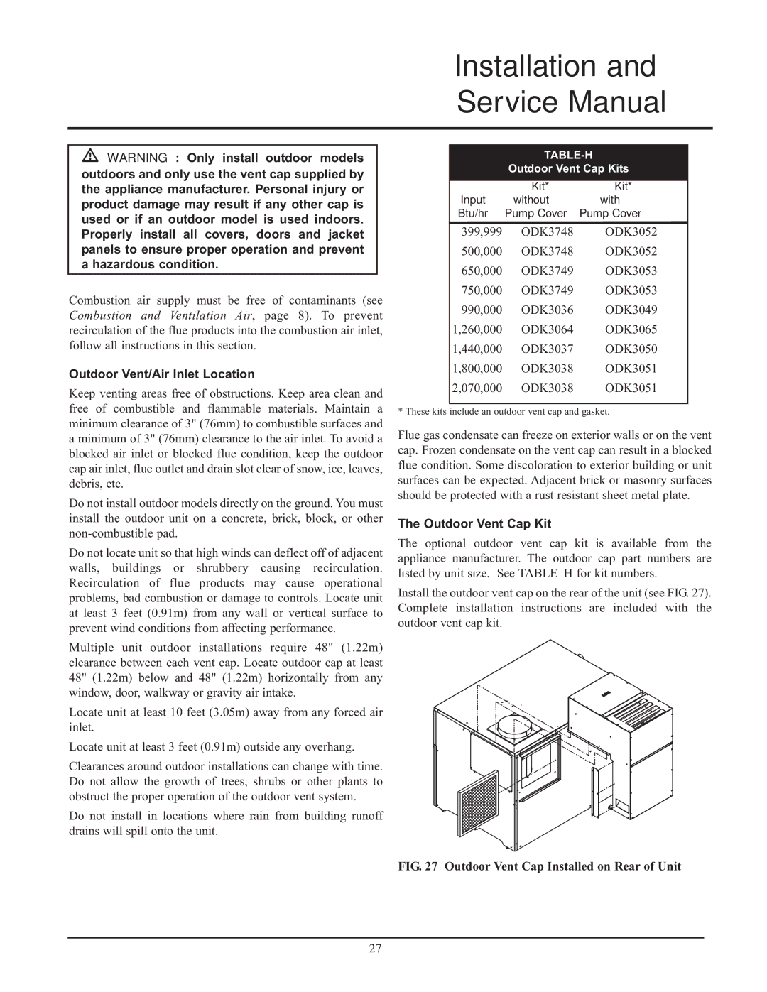
Install the outdoor vent cap on the rear of the unit (see FIG. 27). Complete installation instructions are included with the outdoor vent cap kit.

FIG. 27 Outdoor Vent Cap Installed on Rear of Unit

27

Page 27
Image 27
Lochinvar 999 - 750, CF-CH(E)-i&s-08, 399 service manual Outdoor Vent/Air Inlet Location, Outdoor Vent Cap Kit

399, CF-CH(E)-i&s-08, 999 - 750 specifications

Lochinvar 999 - 750, CF-CH(E)-i&s-08,399 is a cutting-edge boiler designed for commercial heating applications. With its robust construction and high efficiency, this model stands out in the crowded market of heating solutions.

One of the main features of the Lochinvar 999 - 750 is its exceptional thermal efficiency rating. The unit incorporates advanced condensing technology that allows it to recover heat from flue gases, which helps in achieving efficiency levels of up to 99%. This efficiency not only reduces energy consumption but also lowers operational costs, making it an excellent investment for businesses looking to minimize their carbon footprint.

The boiler is designed to provide a powerful output of 750 kW, ensuring it meets the heating demands of larger buildings or commercial spaces. Its capacity makes it suitable for a range of applications including schools, hospitals, and industrial facilities. Moreover, the unit features a built-in cascading system that enables multiple boilers to be connected, enhancing system reliability and flexibility.

In terms of technology, the Lochinvar 999 - 750 is equipped with a user-friendly touchscreen interface. This innovative control system allows operators to monitor and adjust settings with ease, providing real-time performance data and alerts for maintenance needs. The intelligent controls optimize operation to match the heating load, further enhancing energy efficiency.

Safety is a top priority with this model. It is built with multiple safety features such as automatic shut-off valves, pressure relief valves, and flame monitoring systems, ensuring safe operation under various conditions. The unit also adheres to stringent industry standards and regulations, making it a reliable choice for commercial applications.

Furthermore, the Lochinvar 999 - 750 is designed with serviceability in mind. Its compact footprint and accessible components simplify maintenance, reducing downtime and associated costs. The unit also supports a variety of fuel sources, including natural gas, propane, and biodiesel, providing flexibility to meet different facility requirements.

In summary, the Lochinvar 999 - 750, CF-CH(E)-i&s-08,399 represents a blend of efficiency, reliability, and safety in commercial heating. Its advanced technologies and thoughtful design make it a powerful solution for various heating needs, making it an ideal choice for businesses aiming for excellence in energy management and operational efficiency.