Hydronic Heating Boilers and Domestic Water Heaters

OPERATION Continued

Diagnostic Status Indication

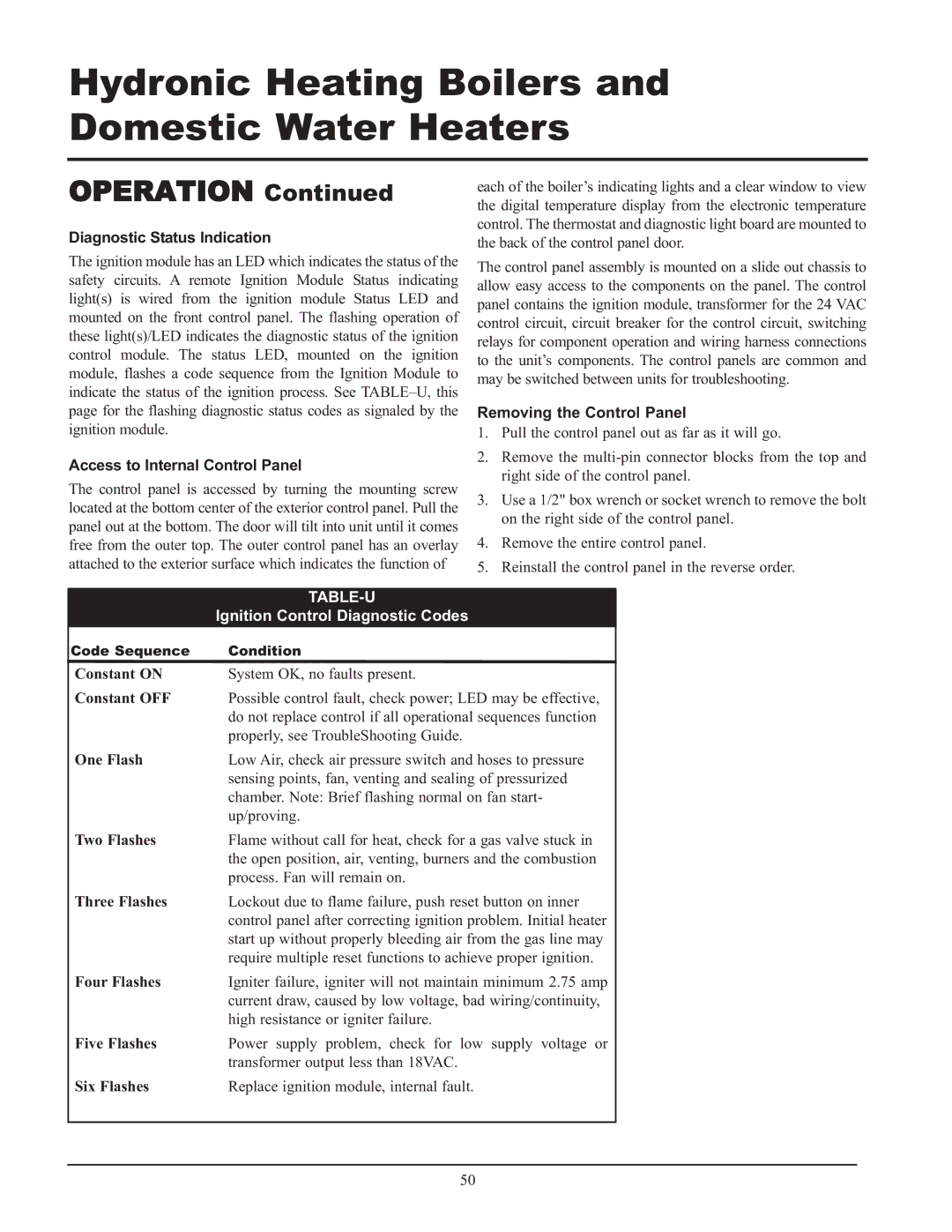
The ignition module has an LED which indicates the status of the safety circuits. A remote Ignition Module Status indicating light(s) is wired from the ignition module Status LED and mounted on the front control panel. The flashing operation of these light(s)/LED indicates the diagnostic status of the ignition control module. The status LED, mounted on the ignition module, flashes a code sequence from the Ignition Module to indicate the status of the ignition process. See TABLE–U, this page for the flashing diagnostic status codes as signaled by the ignition module.

Access to Internal Control Panel

The control panel is accessed by turning the mounting screw located at the bottom center of the exterior control panel. Pull the panel out at the bottom. The door will tilt into unit until it comes free from the outer top. The outer control panel has an overlay attached to the exterior surface which indicates the function of

each of the boiler’s indicating lights and a clear window to view the digital temperature display from the electronic temperature control. The thermostat and diagnostic light board are mounted to the back of the control panel door.

The control panel assembly is mounted on a slide out chassis to allow easy access to the components on the panel. The control panel contains the ignition module, transformer for the 24 VAC control circuit, circuit breaker for the control circuit, switching relays for component operation and wiring harness connections to the unit’s components. The control panels are common and may be switched between units for troubleshooting.

Removing the Control Panel

1.Pull the control panel out as far as it will go.

2.Remove the multi-pin connector blocks from the top and right side of the control panel.

3.Use a 1/2" box wrench or socket wrench to remove the bolt on the right side of the control panel.

4.Remove the entire control panel.

5.Reinstall the control panel in the reverse order.


TABLE-U


Ignition Control Diagnostic Codes


Code Sequence

Condition


Constant ON

System OK, no faults present.


Constant OFF

Possible control fault, check power; LED may be effective,


do not replace control if all operational sequences function


properly, see TroubleShooting Guide.


One Flash

Low Air, check air pressure switch and hoses to pressure


sensing points, fan, venting and sealing of pressurized


chamber. Note: Brief flashing normal on fan start-


up/proving.


Two Flashes

Flame without call for heat, check for a gas valve stuck in


the open position, air, venting, burners and the combustion


process. Fan will remain on.


Three Flashes

Lockout due to flame failure, push reset button on inner


control panel after correcting ignition problem. Initial heater


start up without properly bleeding air from the gas line may


require multiple reset functions to achieve proper ignition.


Four Flashes

Igniter failure, igniter will not maintain minimum 2.75 amp


current draw, caused by low voltage, bad wiring/continuity,


high resistance or igniter failure.


Five Flashes

Power supply problem, check for low supply voltage or


transformer output less than 18VAC.


Six Flashes

Replace ignition module, internal fault.


50

Page 50
Image 50
Lochinvar 399 Diagnostic Status Indication, Access to Internal Control Panel, Removing the Control Panel, Table-U

399, CF-CH(E)-i&s-08, 999 - 750 specifications

Lochinvar 999 - 750, CF-CH(E)-i&s-08,399 is a cutting-edge boiler designed for commercial heating applications. With its robust construction and high efficiency, this model stands out in the crowded market of heating solutions.

One of the main features of the Lochinvar 999 - 750 is its exceptional thermal efficiency rating. The unit incorporates advanced condensing technology that allows it to recover heat from flue gases, which helps in achieving efficiency levels of up to 99%. This efficiency not only reduces energy consumption but also lowers operational costs, making it an excellent investment for businesses looking to minimize their carbon footprint.

The boiler is designed to provide a powerful output of 750 kW, ensuring it meets the heating demands of larger buildings or commercial spaces. Its capacity makes it suitable for a range of applications including schools, hospitals, and industrial facilities. Moreover, the unit features a built-in cascading system that enables multiple boilers to be connected, enhancing system reliability and flexibility.

In terms of technology, the Lochinvar 999 - 750 is equipped with a user-friendly touchscreen interface. This innovative control system allows operators to monitor and adjust settings with ease, providing real-time performance data and alerts for maintenance needs. The intelligent controls optimize operation to match the heating load, further enhancing energy efficiency.

Safety is a top priority with this model. It is built with multiple safety features such as automatic shut-off valves, pressure relief valves, and flame monitoring systems, ensuring safe operation under various conditions. The unit also adheres to stringent industry standards and regulations, making it a reliable choice for commercial applications.

Furthermore, the Lochinvar 999 - 750 is designed with serviceability in mind. Its compact footprint and accessible components simplify maintenance, reducing downtime and associated costs. The unit also supports a variety of fuel sources, including natural gas, propane, and biodiesel, providing flexibility to meet different facility requirements.

In summary, the Lochinvar 999 - 750, CF-CH(E)-i&s-08,399 represents a blend of efficiency, reliability, and safety in commercial heating. Its advanced technologies and thoughtful design make it a powerful solution for various heating needs, making it an ideal choice for businesses aiming for excellence in energy management and operational efficiency.