Commercial Pool Heaters
INSTALLATION
This pool heater meets the safe lighting performance criteria with the gas manifold and control assembly provided, as specified in the ANSI Z21.10.3/CSA 4.3 standard for
LOCATING POOL HEATER
1.Maintain all clearances from combustible construction when locating pool heater. See Clearances from Combustible Construction, this page.
2.Locate the pool heater so that if water connections should leak, water damage will not occur. When such locations cannot be avoided, install a suitable drain pan that is well- drained under the pool heater. The pan must not restrict combustion air flow. The pool heater manufacturer is not responsible for water damage in connection with this pool heater, or any of its components.
3.Install the indoor pool heaters so that the ignition system components are protected from any water while operating or during service.
4.You must install the pool heater on a level, non- combustible floor.
5.Do not install pool heater directly on carpet or other combustible material. A
If installing the pool heater in an area with a combustible floor, you must construct a special combustible floor base. See Base for Combustible Floors, this page.
6.For outdoor models, you must install an optional vent cap. Instructions for mounting the vent cap are included in the venting section. Do not install outdoor models directly on the ground. You must install the outdoor pool heater on a concrete, brick, block, or other
Clearances from Combustible
Construction
Maintain minimum specified clearances for adequate operation. Allow sufficient space for servicing pipe connections, pump and other auxiliary equipment, as well as the pool heater. See rating plate for specific service clearance requirements.
Right Side | 3" | (7.5 cm) |
Rear | 3" | (7.5 cm) (3" min. from any surface) |
Left Side | 6" (15cm) (24" (0.61m) suggested for service) |
Front | Alcove* (30" (0.76m) suggested for service) |
Top | 3" (7.5cm) |
Flue | 1" (25.4mm) |
Hot Water Pipes 1" (25.4mm)
*An Alcove is a closet without a door.
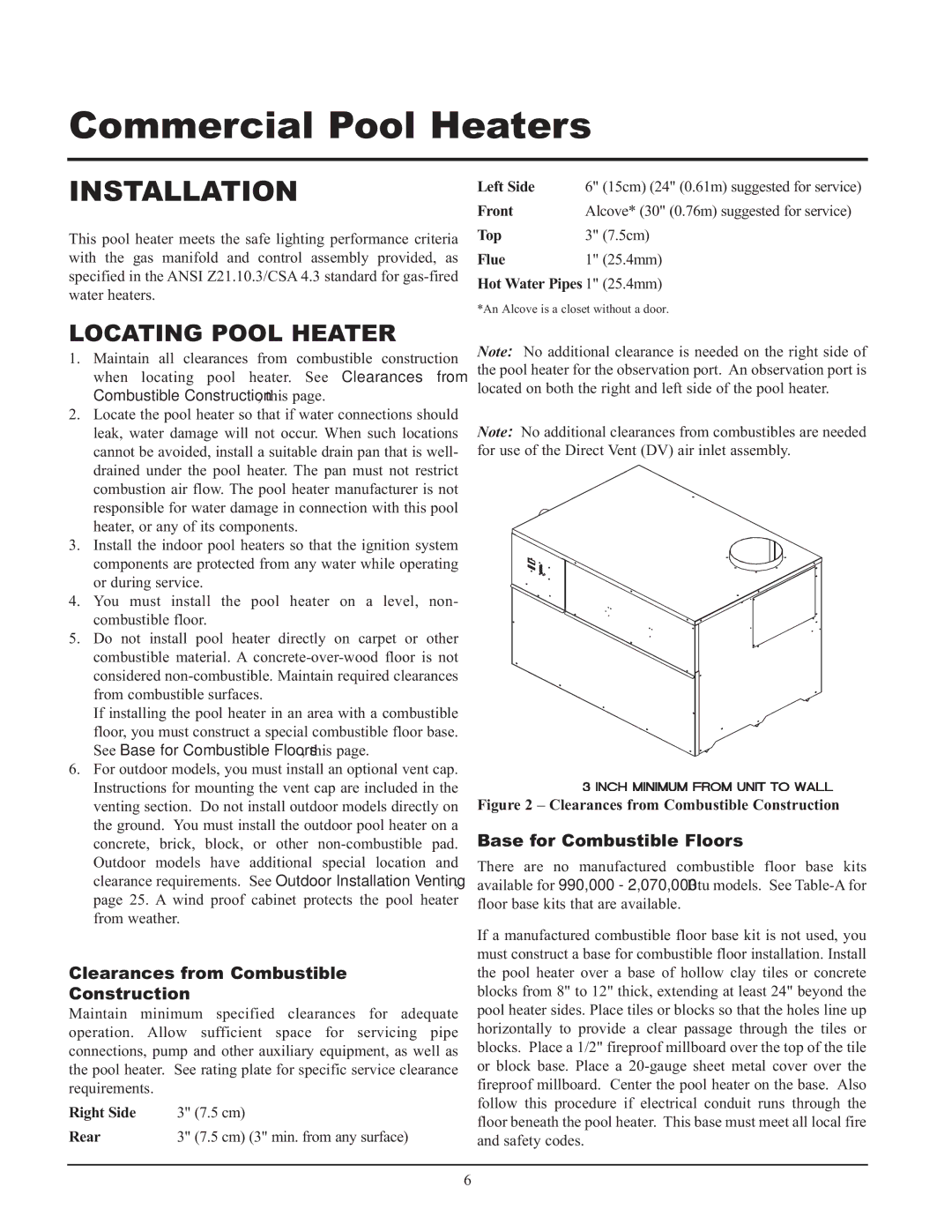
Note: No additional clearance is needed on the right side of the pool heater for the observation port. An observation port is located on both the right and left side of the pool heater.
Note: No additional clearances from combustibles are needed for use of the Direct Vent (DV) air inlet assembly.
Figure 2 – Clearances from Combustible Construction
Base for Combustible Floors
There are no manufactured combustible floor base kits available for 990,000 - 2,070,000 Btu models. See
If a manufactured combustible floor base kit is not used, you must construct a base for combustible floor installation. Install the pool heater over a base of hollow clay tiles or concrete blocks from 8" to 12" thick, extending at least 24" beyond the pool heater sides. Place tiles or blocks so that the holes line up horizontally to provide a clear passage through the tiles or blocks. Place a 1/2" fireproof millboard over the top of the tile or block base. Place a
6