First installation
If a Individual 32 / Individual 32 Selection was retrofitted with a PIP tuner or if this is already integrated in a set with a digital recorder, the PIP tuner output has to be connected with the
If a Digital Satellite Tuner 1 has been retrofitted, connect your satellite antenna system to the
If a Digital Satellite Tuner 2 has been retrofitted (only in conjunction with the Digital Recorder+), then connect one antenna cable each, for example from the antenna switch or from the twin LNC, to both SAT sockets.
Handling the fabric hose
Use the fabric hose included to lay the mains cables, antenna cables or cables from other electronic components systematically; then lead the hose with the cables to the connection boxes. This provides
Using the common interface module
(only for sets with CI slot)
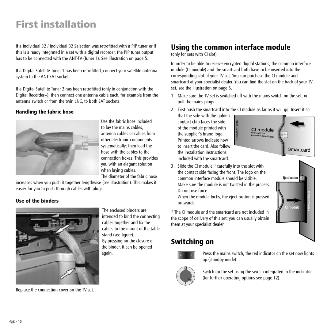
In order to be able to receive encrypted digital stations, the common interface module (CI module) and the smartcard both have to be inserted into the corresponding slot of your TV set. You can purchase the CI module and smartcard at your specialist dealer. You can find the slot on the back of your TV set, see the illustration on page 5.
1. Make sure the TV set is switched off with the mains switch on the set, or pull the mains plugs.
2. First push the smartcard into the CI module as far as it will go. Insert it so
that the side with the golden |
| |
| ||
contact chip faces the side | side | |
of the module printed with | ||
Contact | ||
the supplier‘s brand logo. | ||
Printed arrows indicate how | ||
| ||
to insert the card. Also follow |
| |
| ||
the installation instructions |
| |
included with the smartcard. |
|
you with an elegant solution when laying cables.
The diameter of the fabric hose increases when you push it together lengthwise (see illustration). This makes it easier for you to push through cables with plugs.
Use of the binders
The enclosed binders are intended to bind the connecting cables together and fix the cables to the mount of the table stand (see figure).
3.Slide the CI module (1 carefully into the slot with the contact side facing the front. The logo on the common interface module should be visible.
Make sure the module is not twisted in the process. Do not use force.
When the module locks, the eject button is pressed outwards.
(1 The CI module and the smartcard are not included in the scope of delivery of this set; you can usually obtain them at your specialist dealer.
Eject button ![]()
| INTERFACE |
CI module | COMMON |
|
By pressing on the closure of the binder, it can be opened again.
Replace the connection cover on the TV set.
Switching on
Press the mains switch, the red indicator on the set now lights up (standby mode).
Switch on the set using the switch integrated in the indicator (for further operating options see page 12).
![]() - 10
- 10