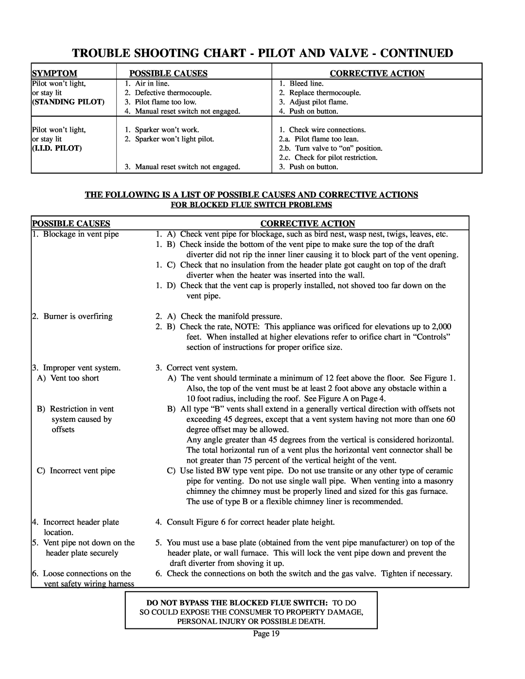
TROUBLE SHOOTING CHART - PILOT AND VALVE - CONTINUED
SYMPTOM | POSSIBLE CAUSES |
| CORRECTIVE ACTION | ||
Pilot won’t light, | 1. | Air in line. | 1. | Bleed line. |
|
or stay lit | 2. | Defective thermocouple. | 2. | Replace thermocouple. | |
(STANDING PILOT) | 3. | Pilot flame too low. | 3. | Adjust pilot flame. | |
| 4. | Manual reset switch not engaged. | 4. | Push on button. | |
Pilot won’t light, | 1. | Sparker won’t work. | 1. | Check wire connections. | |
or stay lit | 2. | Sparker won’t light pilot. | 2.a. Pilot flame too lean. | ||
(I.I.D. PILOT) |
|
| 2.b. Turn valve to “on” position. | ||
|
|
| 2.c. Check for pilot restriction. | ||
| 3. | Manual reset switch not engaged. | 3. | Push on button. | |
|
|
|
|
|
|
THE FOLLOWING IS A LIST OF POSSIBLE CAUSES AND CORRECTIVE ACTIONS
FOR BLOCKED FLUE SWITCH PROBLEMS
POSSIBLE CAUSES |
|
| CORRECTIVE ACTION | ||||
|
|
|
|
| |||
1. | Blockage in vent pipe | 1. | A) | Check vent pipe for blockage, such as bird nest, wasp nest, twigs, leaves, etc. | |||
|
|
|
| 1. | B) | Check inside the bottom of the vent pipe to make sure the top of the draft | |
|
|
|
|
|
| diverter did not rip the inner liner causing it to block part of the vent opening. | |
|
|
|
| 1. | C) | Check that no insulation from the header plate got caught on top of the draft | |
|
|
|
|
|
| diverter when the heater was inserted into the wall. | |
|
|
|
| 1. | D) | Check that the vent cap is properly installed, not shoved too far down on the | |
|
|
|
|
|
| vent pipe. | |
2. | Burner is overfiring | 2. | A) | Check the manifold pressure. | |||
|
|
|
| 2. | B) | Check the rate, NOTE: This appliance was orificed for elevations up to 2,000 | |
|
|
|
|
|
| feet. When installed at higher elevations refer to orifice chart in “Controls” | |
|
|
|
|
|
| section of instructions for proper orifice size. | |
3. | Improper vent system. | 3. | Correct vent system. | ||||
A) | Vent too short |
| A) | The vent should terminate a minimum of 12 feet above the floor. See Figure 1. | |||
|
|
|
|
|
| Also, the top of the vent must be at least 2 foot above any obstacle within a | |
|
|
|
|
|
| 10 foot radius, including the roof. See Figure A on Page 4. | |
B) | Restriction in vent |
| B) | All type “B” vents shall extend in a generally vertical direction with offsets not | |||
|
| system caused by |
|
| exceeding 45 degrees, except that a vent system having not more than one 60 | ||
|
| offsets |
|
| degree offset may be allowed. | ||
|
|
|
|
|
| Any angle greater than 45 degrees from the vertical is considered horizontal. | |
|
|
|
|
|
| The total horizontal run of a vent plus the horizontal vent connector shall be | |
|
|
|
|
|
| not greater than 75 percent of the vertical height of the vent. | |
C) | Incorrect vent pipe |
| C) | Use listed BW type vent pipe. Do not use transite or any other type of ceramic | |||
|
|
|
|
|
| pipe for venting. Do not use single wall pipe. When venting into a masonry | |
|
|
|
|
|
| chimney the chimney must be properly lined and sized for this gas furnace. | |
|
|
|
|
|
| The use of type B or a flexible chimney liner is recommended. | |
4. | Incorrect header plate | 4. | Consult Figure 6 for correct header plate height. | ||||
| location. |
|
|
|
| ||
5. | Vent pipe not down on the | 5. | You must use a base plate (obtained from the vent pipe manufacturer) on top of the | ||||
|
| header plate securely |
| header plate, or wall furnace. This will lock the vent pipe down and prevent the | |||
|
|
|
|
| draft diverter from shoving it up. | ||
6. | Loose connections on the | 6. | Check the connections on both the switch and the gas valve. Tighten if necessary. | ||||
| vent safety wiring harness |
|
|
|
| ||
|
|
|
|
|
| ||
|
|
|
| DO NOT BYPASS THE BLOCKED FLUE SWITCH: TO DO |
| ||
|
|
|
| SO COULD EXPOSE THE CONSUMER TO PROPERTY DAMAGE, |
| ||
|
|
|
|
|
| PERSONAL INJURY OR POSSIBLE DEATH. |
|
|
|
|
|
|
|
|
|
Page 19