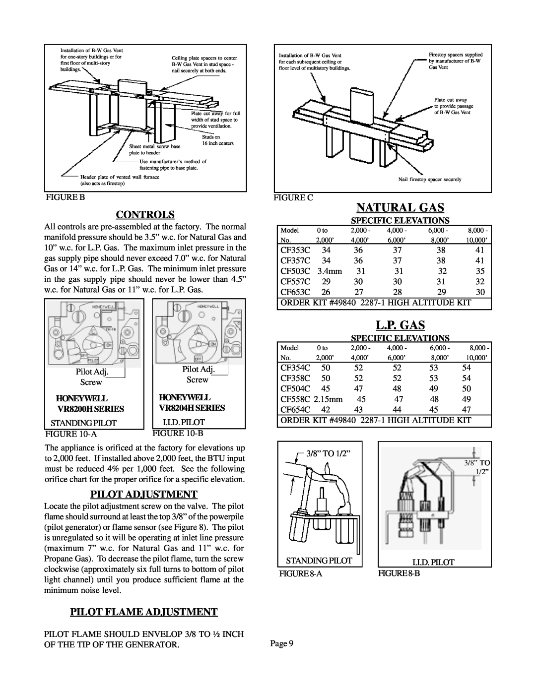
Installation of |
|
for | Ceiling plate spacers to center |
first floor of | |
buildings. | nail securely at both ends. |
Plate cut away for full width of stud space to provide ventilation.
Installation of
Firestop spacers supplied by manufacturer of
Plate cut away
to provide passage of
Sheet metal screw base plate to header
Studs on
16 inch centers
Use manufacturer’s method of fastening pipe to base plate.
Header plate of vented wall furnace (also acts as firestop)
FIGURE B
CONTROLS
All controls are
Nail firestop spacer securely
FIGURE C
NATURAL GAS
SPECIFIC ELEVATIONS
Model | 0 to | 2,000 - | 4,000 - | 6,000 - | 8,000 - |
No. | 2,000’ | 4,000’ | 6,000’ | 8,000’ | 10,000’ |
CF353C | 34 | 36 | 37 | 38 | 41 |
CF357C | 34 | 36 | 37 | 38 | 41 |
CF503C | 3.4mm | 31 | 31 | 32 | 35 |
CF557C | 29 | 30 | 30 | 31 | 32 |
CF653C | 26 | 27 | 28 | 29 | 30 |
ORDER KIT #49840
L.P. GAS
SPECIFIC ELEVATIONS
Pilot Adj.
Screw
HONEYWELL VR8200H SERIES
STANDING PILOT
FIGURE
Pilot Adj.
Screw
HONEYWELL VR8204H SERIES
I.I.D. PILOT
FIGURE
Model | 0 to | 2,000 - | 4,000 - | 6,000 - | 8,000 - |
No. | 2,000’ | 4,000’ | 6,000’ | 8,000’ | 10,000’ |
CF354C | 50 | 52 | 52 | 53 | 54 |
CF358C | 50 | 52 | 52 | 53 | 54 |
CF504C | 45 | 47 | 48 | 49 | 50 |
CF558C 2.15mm | 45 | 47 | 48 | 49 | |
CF654C | 42 | 43 | 44 | 45 | 47 |
ORDER KIT #49840 | |||||
|
|
|
|
|
|
The appliance is orificed at the factory for elevations up to 2,000 feet. If installed above 2,000 feet, the BTU input must be reduced 4% per 1,000 feet. See the following orifice chart for the proper orifice for a specific elevation.
PILOT ADJUSTMENT
Locate the pilot adjustment screw on the valve. The pilot flame should surround at least the top 3/8” of the powerpile (pilot generator) or flame sensor (see Figure 8). The pilot is unregulated so it will be operating at inlet line pressure (maximum 7” w.c. for Natural Gas and 11” w.c. for Propane Gas). To decrease the pilot flame, turn the screw clockwise (approximately six full turns to bottom of pilot light channel) until you produce sufficient flame at the minimum noise level.
PILOT FLAME ADJUSTMENT
3/8” TO 1/2” |
3/8” TO |
1/2” |
STANDING PILOT |
| I.I.D. PILOT |
FIGURE |
|
PILOT FLAME SHOULD ENVELOP 3/8 TO ½ INCH | Page 9 |
OF THE TIP OF THE GENERATOR. |