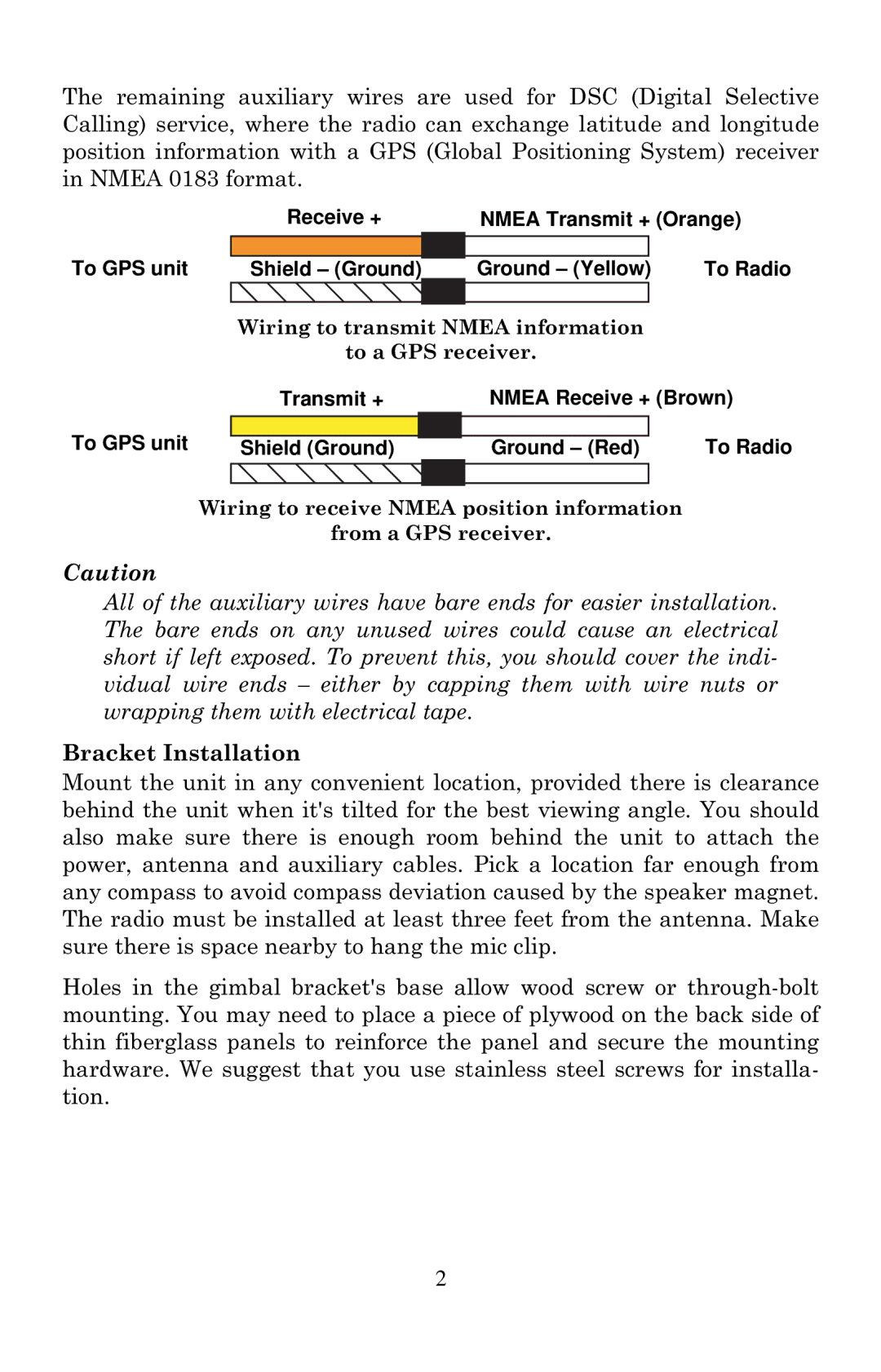
The remaining auxiliary wires are used for DSC (Digital Selective Calling) service, where the radio can exchange latitude and longitude position information with a GPS (Global Positioning System) receiver in NMEA 0183 format.
|
| Receive + | NMEA Transmit + (Orange) | |||
To GPS unit |
|
|
|
| To Radio | |
Shield – (Ground) |
| Ground – (Yellow) |
| |||
|
|
|
|
|
|
|
|
| Wiring to transmit NMEA information |
| |||
|
| to a GPS receiver. |
| |||
|
| Transmit + | NMEA Receive + (Brown) | |||
To GPS unit |
|
|
|
|
| To Radio |
|
|
|
|
| ||
| Shield (Ground) |
| Ground – (Red) |
| ||
|
|
|
|
|
|
|
Wiring to receive NMEA position information
from a GPS receiver.
Caution
All of the auxiliary wires have bare ends for easier installation. The bare ends on any unused wires could cause an electrical short if left exposed. To prevent this, you should cover the indi- vidual wire ends – either by capping them with wire nuts or wrapping them with electrical tape.
Bracket Installation
Mount the unit in any convenient location, provided there is clearance behind the unit when it's tilted for the best viewing angle. You should also make sure there is enough room behind the unit to attach the power, antenna and auxiliary cables. Pick a location far enough from any compass to avoid compass deviation caused by the speaker magnet. The radio must be installed at least three feet from the antenna. Make sure there is space nearby to hang the mic clip.
Holes in the gimbal bracket's base allow wood screw or
2