P 8/ 25
 Repair
[3]DISASSEMBLY/ASSEMBLY
[3]-5. Shear Blade (cont.)
ASSEMBLING
(4)Mount Shear blade assembly in the Gear case while fitting Shear blade’ boss into the hole of Connecting rod. Fix the Shear blade assembly to Gear case by driving Hex socket head bolt through the Holder and
each Sleeve 5.
Note: • Do not forget to mount Seal. (Fig. 14)
•Apply Makita grease N. No.2 to the portion designated with black triangle. (Fig. 15)
Fig. 14
Spur gear 43 |
|
Holder | Seal |
Boss |
|
Gear case |
|
Fig. 15
![]()
![]() Connecting rod
Connecting rod
Cam portion
Apply the both of Cam portions which accept Connecting rods.
![]() Connecting rod
Connecting rod
ADJUSTMENT
(1)Loosen Hex lock nut.
(2)After tightening Hex socket button head bolt, turn it back by 1/4 to 3/8 counterclockwise.
(3)Tighten Hex lock nut fully while locking Hex socket button head bolt with Hex wrench. (Fig. 16)
Fig. 16
Lock Hex socket button head bolt.
Tighten Hex lock nut.
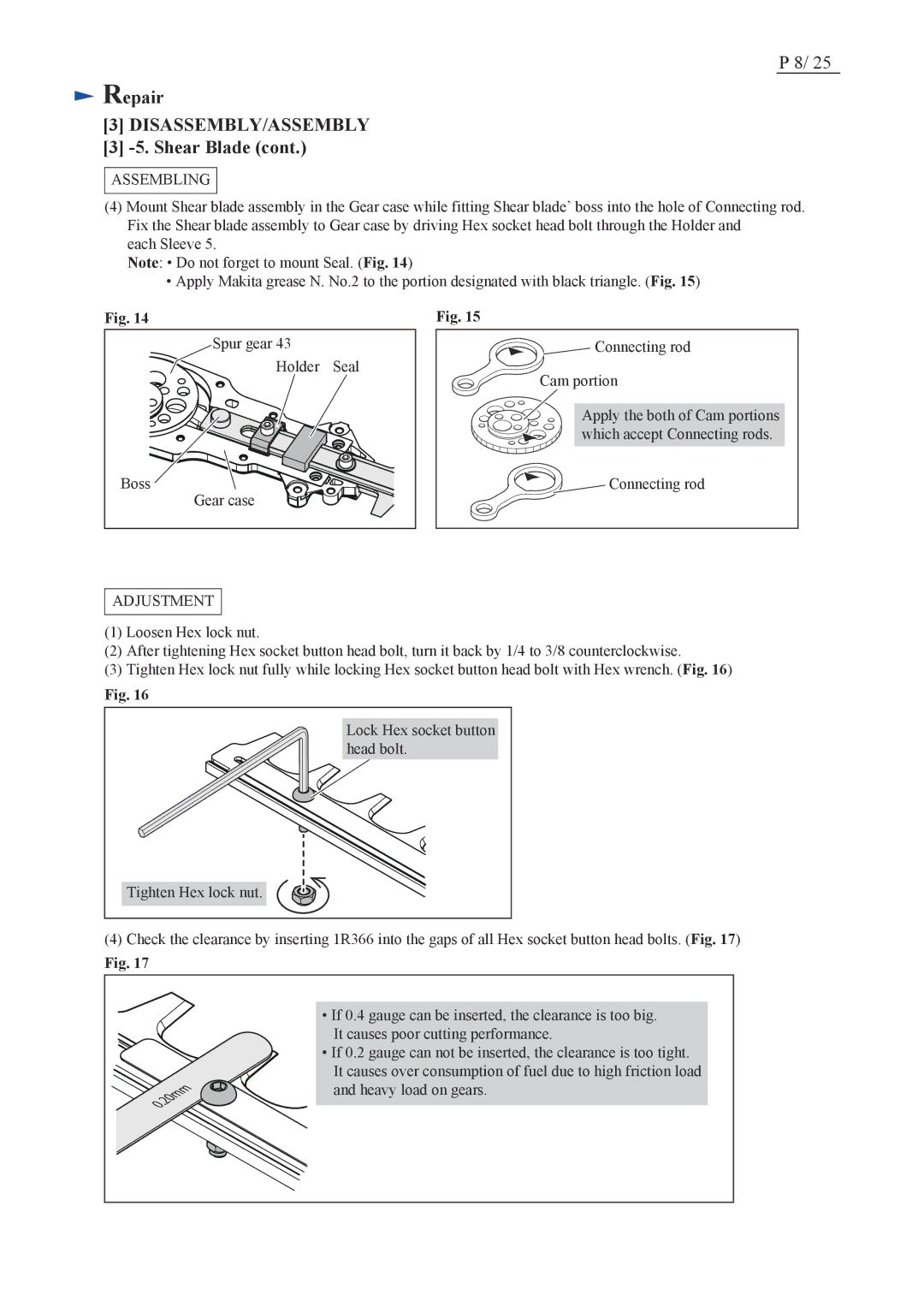
(4)Check the clearance by inserting 1R366 into the gaps of all Hex socket button head bolts. (Fig. 17)
Fig. 17
•If 0.4 gauge can be inserted, the clearance is too big. It causes poor cutting performance.
•If 0.2 gauge can not be inserted, the clearance is too tight. It causes over consumption of fuel due to high friction load
and heavy load on gears.