P 2/ 20
 Repair
CAUTION: Remove the hammer bit from the machine and disconnect the Machine from power source for safety before repair/ maintenance in accordance with the instruction manual!
[1] NECESSARY REPAIRING TOOLS
Code No. | Description | Use for | |
|
|
|
|
1R003 | Retaining ring S pliers | Removing Ring spring 26 | |
|
|
|
|
1R212 | Tip for Retaining Ring Pliers | Attaching to 1R003, when removing Ring spring 26 | |
|
|
|
|
1R023 | Pipe Ring (for Arbor press) | Removing Ball bearing | |
|
|
|
|
1R024 | Press Tool (for Arbor press) | Pressing down Slide sleeve for easy removing of Ring spring 43 | |
|
|
|
|
1R031 | Bearing setting pipe | Assembling Helical gear 52 | |
|
|
|
|
1R045 | Gear extractor (large) | Removing Counter shaft | |
|
|
|
|
1R346 | Center Attachment | Attaching to 1R045, when removing Counter shaft | |
|
|
| |
1R165 | Gear extractor (large) | Supporting Crank shaft for assembling Helical gear 52 |
|
|
|
|
|
1R214 | Taper sleeve | Fitting Fluoride ring 28 on Impact bolt | |
|
|
|
|
1R217 | Ring 22 | Removing / Assembling Crank shaft | |
|
|
|
|
1R228 | 1/4” Hex Shank bit for M4 | Removing M4 Hex socket head bolts | |
|
|
|
|
1R230 | 1/4” Hex Shank bit for M6 | Removing M6 Hex socket head bolts | |
|
|
|
|
1R231 | 1/4” Hex Shank bit for M8 | Removing M8 Hex socket head bolts | |
|
|
|
|
1R246 | Round Bar for Arbor | Removing M8 Hex socket head bolts | |
|
|
|
|
1R247 | Round Bar for Arbor | Removing Ball bearing 6203LLB | |
|
|
|
|
1R263 | Bearing Extractor | Separating Cylinder 40 and Motor housing from Crank housing | |
|
|
|
|
1R269 | Bearing Extractor (small) | Removing Ball bearing 6000DDW from Commutator end of Armature | |
|
|
|
|
1R291 | Retaining ring S & R pliers | Removing Retaining ring | |
|
|
|
|
1R306 | Ring spring removing Jig | Disassembling AVT mechanism | |
|
|
|
|
1R363 | Ring spring removing tool | Pressing down Flat washer 30 for easy removing Ring spring 26 | |
|
|
|
|
[2] LUBRICATIONS
[2] - 1 Tool holder section
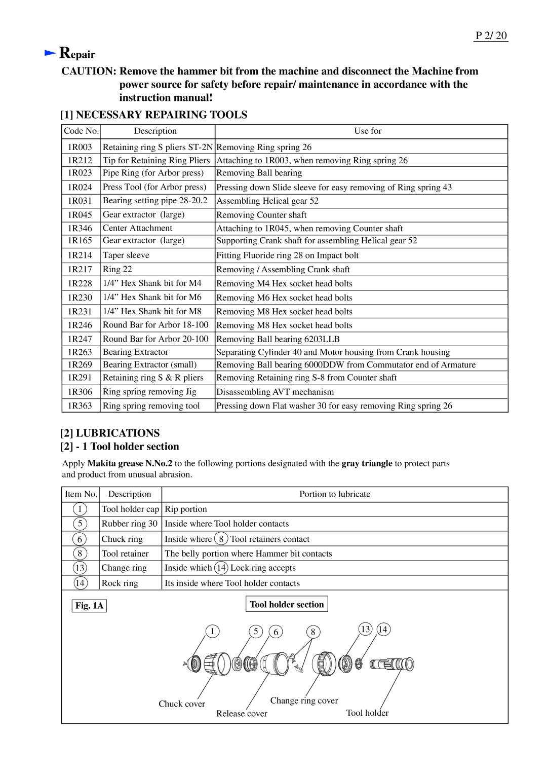
Apply Makita grease N.No.2 to the following portions designated with the gray triangle to protect parts and product from unusual abrasion.
Item No. | Description | Portion to lubricate |
|
|
|
1 | Tool holder cap | Rip portion |
|
|
|
5 | Rubber ring 30 | Inside where Tool holder contacts |
|
|
|
6 | Chuck ring | Inside where 8 Tool retainers contact |
|
|
|
8 | Tool retainer | The belly portion where Hammer bit contacts |
|
|
|
13 | Change ring | Inside which 14 Lock ring accepts |
|
|
|
14 | Rock ring | Its inside where Tool holder contacts |
|
|
|
Fig. 1A
Tool holder section
1 | 5 | 6 | 8 | 13 | 14 |
Chuck cover | Change ring cover | |
Tool holder | ||
Release cover |
