P 20/ 20
 Wiring diagram
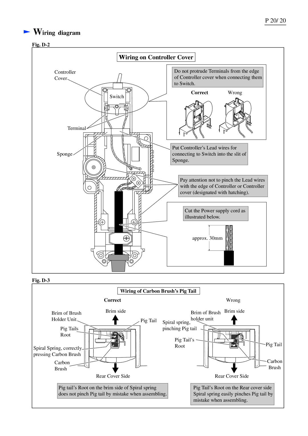
Fig. D-2
wiring on Controller Cover
Controller
Cover
Switch
Terminal![]()
Sponge
Do not protrude Terminals from the edge of Controller cover when connecting them to Switch.
Correct Wrong
Put Controller’s Lead wires for connecting to Switch into the slit of Sponge.
Pay attention not to pinch the Lead wires with the edge of Controller or Controller cover (designated with hatching).
Cut the Power supply cord as illustrated below.
approx. 30mm
Fig. D-3
Wiring of Carbon Brush’s Pig Tail |
|
Correct | Wrong |
Brim of Brush | Brim side |
| |
Holder Unit |
|
Pig Tails
Root
Spiral Spring, correctly![]() pressing Carbon Brush
pressing Carbon Brush
Brim of Brush Brim side
Pig Tail Spiral spring,holder unit pinching Pig tail
Pig Tail’s | Pig Tail | |
Root | ||
|
Carbon | Carbon |
Brush | Brush |
Rear Cover Side | Rear Cover Side |
Pig tail’s Root on the brim side of Spiral spring does not pinch Pig tail by mistake when assembling.
Pig Tail’s Root on the Rear cover side Spiral spring easily pinches Pig tail by mistake when assembling.