P 12/ 20
 Repair
[3] DISASSEMBLY/ASSEMBLY
[3]-4. Bearing box section, Crank housing section
ASSEMBLING
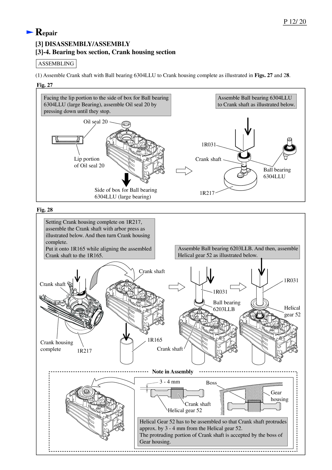
(1)Assemble Crank shaft with Ball bearing 6304LLU to Crank housing complete as illustrated in Figs. 27 and 28.
Fig. 27
Facing the lip portion to the side of box for Ball bearing 6304LLU (large Bearing), assemble Oil seal 20 by pressing down until they stop.
Oil seal 20 ![]()
![]()
Lip portion of Oil seal 20
Assemble Ball bearing 6304LLU to Crank shaft as illustrated below.
1R031
Crank shaft
Ball bearing 6304LLU
Side of box for Ball bearing | 1R217 | |
6304LLU (large bearing) | ||
|
Fig. 28
Setting Crank housing complete on 1R217, assemble the Crank shaft with arbor press as illustrated below. And then turn Crank housing complete.
Put it onto 1R165 while aligning the assembled Crank shaft to the 1R165.
Assemble Ball bearing 6203LLB. And then, assemble Helical gear 52 as illustrated below.
Crank shaft
Crank housing
complete 1R217
Crank shaft
1R165
Crank shaft
1R031
![]() 1R031
1R031 ![]()
Ball bearing | Helical |
6203LLB | |
| gear 52 |
Note in Assembly |
|
3 - 4 mm | Boss |
| Gear |
| housing |
Crank shaft | |
Helical gear 52 |
|
Helical Gear 52 has to be assembled so that Crank shaft protrudes approx. by 3 - 4 mm from the Helical gear 52.
The protruding portion of Crank shaft is accepted by the boss of Gear housing.
