P 3/16
 Repair
[3]DISASSEMBLY/ASSEMBLY
[3]-1. Base
DISASSEMBLING
Set the cutting depth of the machine to maximum, and remove saw blade.
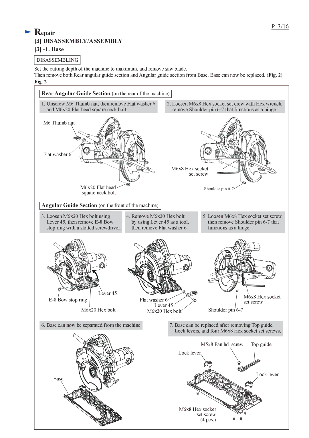
Then remove both Rear angular guide section and Angular guide section from Base. Base can now be replaced. (Fig. 2)
Fig. 2
Rear Angular Guide Section (on the rear of the machine)
1.Unscrew M6 Thumb nut, then remove Flat washer 6 and M6x20 Flat head square neck bolt.
2.Loosen M6x8 Hex socket set crew with Hex wrench, remove Shoulder pin
M6 Thumb nut
Flat washer 6
M6x8 Hex socket![]() set screw
set screw
M6x20 Flat head | Shoulder pin |
square neck bolt |
|
Angular Guide Section (on the front of the machine)
3.Loosen M6x20 Hex bolt using Lever 45, then remove
4.Remove M6x20 Hex bolt by using Lever 45 as a tool, then remove Flat washer 6.
5.Loosen M6x8 Hex socket set screw, then remove Shoulder pin
Lever 45 |
| M6x8 Hex socket | |
Flat washer 6 | |||
set screw | |||
| Lever 45 | ||
M6x20 Hex bolt | Shoulder pin | ||
M6x20 Hex bolt |
6. Base can now be separated from the machine.
Base
7.Base can be replaced after removing Top guide, Lock levers, and four M6x8 Hex socket set screws.
M5x8 Pan hd. screw Top guide Lock lever
Lock lever
M6x8 Hex socket set screw (4 pcs.)