Manuals
/
Manitowoc Ice
/
Kitchen Appliance
/
Ice Maker
Manitowoc Ice
S1000M Water Supply And Drain Line Sizing/Connections, Installation Instructions
Models:
S1000M
1
14
38
38
Download
38 pages
21.14 Kb
11
12
13
14
15
16
17
18
Install
Warranty
Maintenance
Problem
Accessories
Dump Valve Disassembly
Sanitizing Procedure
Water Purge Adjustment
Cleaning Procedure
How to
Page 14
Image 14
Page 13
Page 15
Page 14
Image 14
Page 13
Page 15
Contents
Installation Use and Care Manual
S1000M Model Ice Machines
Safety Notices
Read These Before Proceeding
PERSONAL INJURY POTENTIAL
Procedural Notices
Manitowoc Cleaner and Sanitizer
Table of Contents continued Section General Information
Section Installation Instructions
AuCS Automatic Cleaning System
Section Before Calling For Service
Table of Contents continued Section Ice Machine Operation
Section Maintenance
Guardian Sachet Replacement Frequency
Section
How to Read a Model Number
Section General Information
General Information
AUCS AUTOMATIC CLEANING SYSTEM
Accessories
MANITOWOC CLEANER AND SANITIZER
BIN CASTER
MODEL/SERIAL PLATE LOCATION
Model/Serial Number Location
Model/Serial Number Location
AUTHORIZED WARRANTY SERVICE
Owner Warranty Registration Card
Warranty Coverage
Service Calls
Ice Machine Dimensions
Section Installation Instructions
Installation Instructions
Width, Depth, and Height Dimensions
The location must be free of airborne and other contaminants
Location of Ice Machine
Ice Machine Heat of Rejection
FUSE/CIRCUIT BREAKER
Electrical Service
VOLTAGE
MINIMUM CIRCUIT AMPACITY
SELF CONTAINED ICE MACHINE 115/1/60 OR 208-230/1/60
Self-Contained Electrical Wiring Connections
For United Kingdom Only
SELF CONTAINED ICE MACHINE 208-230/3/60
WATER SUPPLY
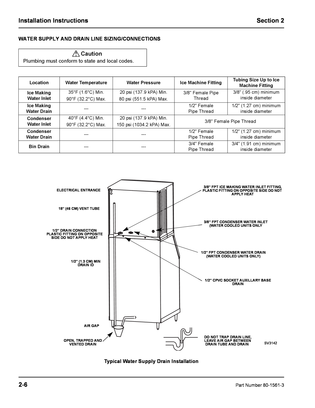
Water Supply and Drain Requirements
Cooling Tower Applications Water-Cooled Models
AIR GAP
Plumbing must conform to state and local codes
Typical Water Supply Drain Installation
WATER SUPPLY AND DRAIN LINE SIZING/CONNECTIONS
Installation Check List
Is the Ice Machine level?
Before Starting the Ice Machine
Potential Personal Injury Situation
Component Identification
Section Ice Machine Operation
Ice Machine Operation
sv3149
2. Refrigeration System Start-Up
Sequence Of Operation
INITIAL START-UP OR START-UP AFTER AUTOMATIC SHUT-OFF 1. Water Purge
FREEZE SEQUENCE 3. Prechill
6. Harvest
SAFETY TIMERS
HARVEST SEQUENCE 5. Water Purge
AUTOMATIC SHUT-OFF 7. Automatic Shut-Off
ICE THICKNESS CHECK
Operational Checks
WATER LEVEL
Ice Thickness Check
45 second setting 0 second setting
Water Purge Adjustment
HARVEST SEQUENCE WATER PURGE
THIS PAGE INTENTIONALLY LEFT BLANK
Exterior Cleaning
Section Maintenance
Maintenance
Ice Machine Inspection
CLEAN UP PROCEDURE FOR DAMAGED SACHET PACKET
SACHET INSTALLATION/REPLACEMENT PROCEDURE
Guardian Location GUARDIAN SACHET REPLACEMENT FREQUENCY
Guardian
Step
Interior Cleaning and Sanitizing
CLEANING PROCEDURE
Remove all ice from the bin
SANITIZING PROCEDURE
Refer to Removal of Parts For Cleaning
16 oz 500 ml cleaner
REMOVAL OF PARTS FOR CLEANING/SANITIZING
Cleaner
1 gal. 4 l
2. Ice Thickness Probe
1. Water Curtain
Water Curtain Removal
Ice Thickness Probe Removal
Water Distribution Tube Removal
3. Water Distribution Tube
4. Water Trough
Water Pump Removal
Water Level Probe
Water Pump
PLUNGER SPRING STOP
Dump Valve Disassembly
Water Dump Valve
COIL SPRING
Drain Line Check Valve
4-10
Evaporator Tray Removal
Water Inlet Valve
Removing the Front Panel
4-11
Panel Removal
4-12
Removal from Service/Winterization
Pry Open the Water Regulating Valve AUCS→ Accessory
SELF-CONTAINED WATER-COOLED ICE MACHINES
Checklist
Section Before Calling For Service
Before Calling For Service
Problem
Safety Limit Feature
Call for service
Page
MANITOWOC ICE, INC
2004 Manitowoc Ice, Inc. Litho in U.S.A
Top
Page
Image
Contents