2 MAINTENANCE
PROCEDURES | |
|
|
PRESSURE SETTING
When the hydraulic cylinders used in the
1.Disconnect and lock out power using the procedure on page
2.Using the quick disconnects, disconnect the hydraulic hoses from the compactor.
3.Remove the 1/4” plug from the check valve and install a
4.Loosen the lock nut on the relief valve and turn the adjustment screw several turns counter clockwise.
5.Remove the lock out provisions and turn the disconnect to the ON position. Start the power unit using the OPERATING INSTRUCTIONS on page
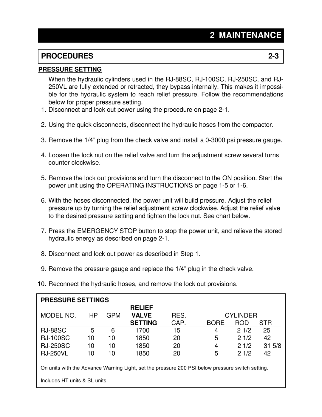
6.With the hoses disconnected, the power unit will build pressure. Adjust the relief pressure up by turning the relief adjustment screw clockwise. Adjust the relief valve to the desired pressure setting and tighten the lock nut. See chart below.
7.Press the EMERGENCY STOP button to stop the power unit, and relieve the stored hydraulic energy as described on page
8.Disconnect and lock out power as described in Step 1.
9.Remove the pressure gauge and replace the 1/4” plug in the check valve.
10.Reconnect the hydraulic hoses, and remove the lock out provisions.
PRESSURE SETTINGS |
|
|
|
|
| ||
|
|
| RELIEF |
|
|
|
|
MODEL NO. | HP | GPM | VALVE | RES. |
| CYLINDER |
|
|
|
| SETTING | CAP. | BORE | ROD | STR |
| 5 | 6 | 1700 | 15 | 4 | 2 1/2 | 25 |
| 10 | 10 | 1850 | 20 | 5 | 2 1/2 | 42 |
| 10 | 10 | 1850 | 20 | 4 | 2 1/2 | 31 5/8 |
| 10 | 10 | 1850 | 20 | 5 | 2 1/2 | 42 |
On units with the Advance Warning Light, set the pressure 200 PSI below pressure switch setting.
Includes HT units & SL units.