3 INSTALLATION
| |
|
|
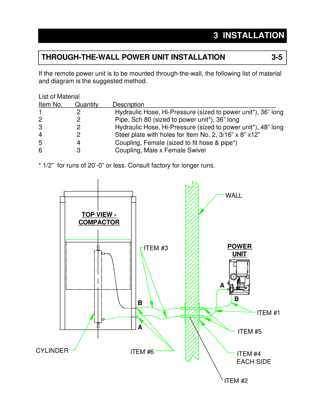
If the remote power unit is to be mounted
List of Material |
|
| |
Item No. | Quantity | Description |
|
1 | 2 | Hydraulic Hose, | |
2 | 2 | Pipe, Sch 80 (sized to power unit*), 36” long | |
3 | 2 | Hydraulic Hose, | |
4 | 2 | Steel plate with holes for Item No. 2, 3/16” x 8” x12” | |
5 | 4 | Coupling, Female (sized to fit hose & pipe*) | |
6 | 3 | Coupling, Male x Female Swivel | |
* 1/2” for runs of
TOP VIEW -
COMPACTOR
ITEM #3
B
A
CYLINDER | ITEM #6 |
![]() WALL
WALL
POWER
UNIT
A
![]() B
B
ITEM #1
ITEM #5
ITEM #4
EACH SIDE
ITEM #2