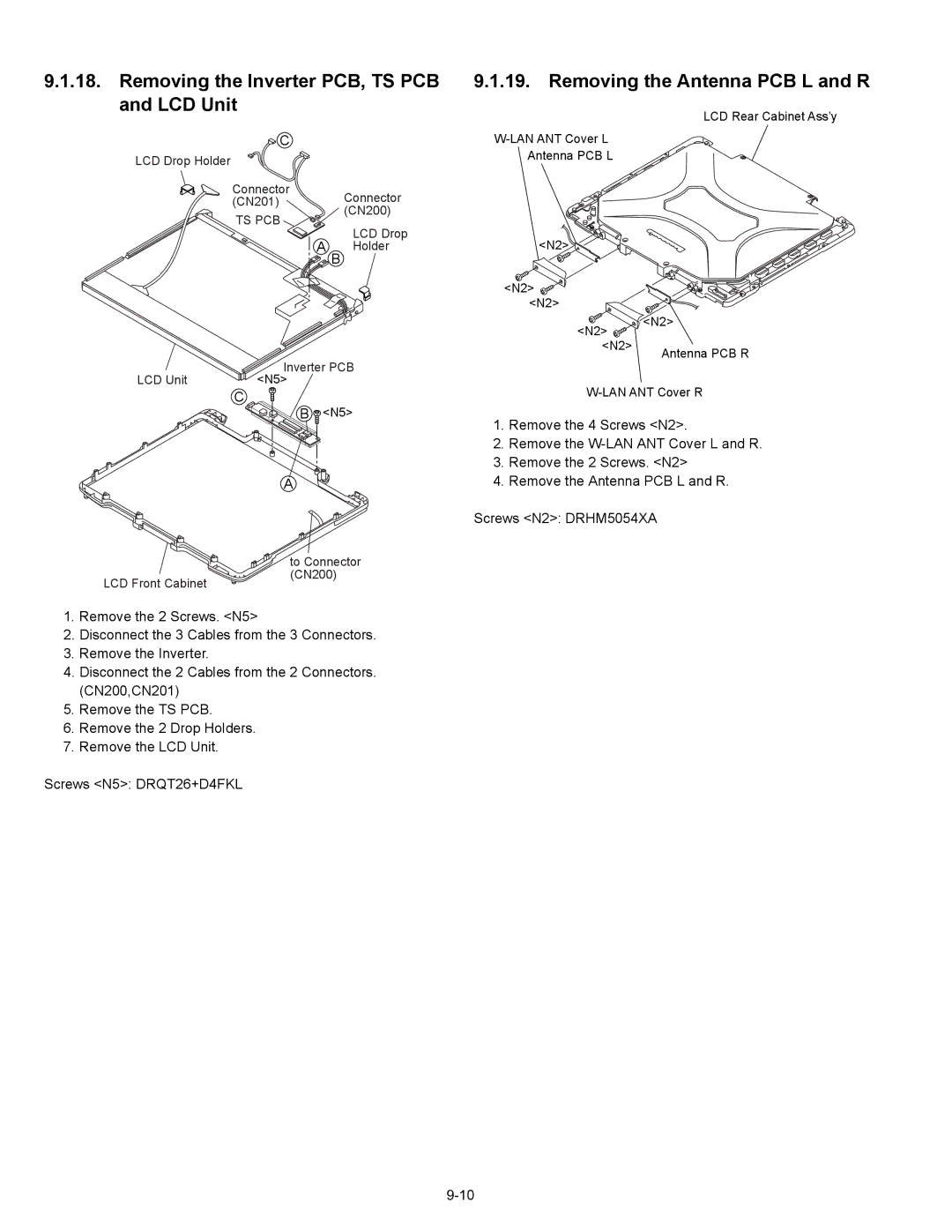
9.1.18. Removing the Inverter PCB, TS PCB and LCD Unit
![]() C
C
LCD Drop Holder
Connector
(CN201) Connector (CN200)
TS PCB
LCD Drop
A B Holder
LCD Unit | Inverter PCB |
<N5> |
C
B ![]() <N5>
<N5>
A
9.1.19. Removing the Antenna PCB L and R
LCD Rear Cabinet Ass’y
Antenna PCB L
<N2>
<N2> ![]() <N2>
<N2>
<N2> | <N2> |
| |
<N2> | Antenna PCB R |
|
1.Remove the 4 Screws <N2>.
2.Remove the
3.Remove the 2 Screws. <N2>
4.Remove the Antenna PCB L and R.
Screws <N2>: DRHM5054XA
LCD Front Cabinet
to Connector (CN200)
1.Remove the 2 Screws. <N5>
2.Disconnect the 3 Cables from the 3 Connectors.
3.Remove the Inverter.
4.Disconnect the 2 Cables from the 2 Connectors. (CN200,CN201)
5.Remove the TS PCB.
6.Remove the 2 Drop Holders.
7.Remove the LCD Unit.
Screws <N5>: DRQT26+D4FKL