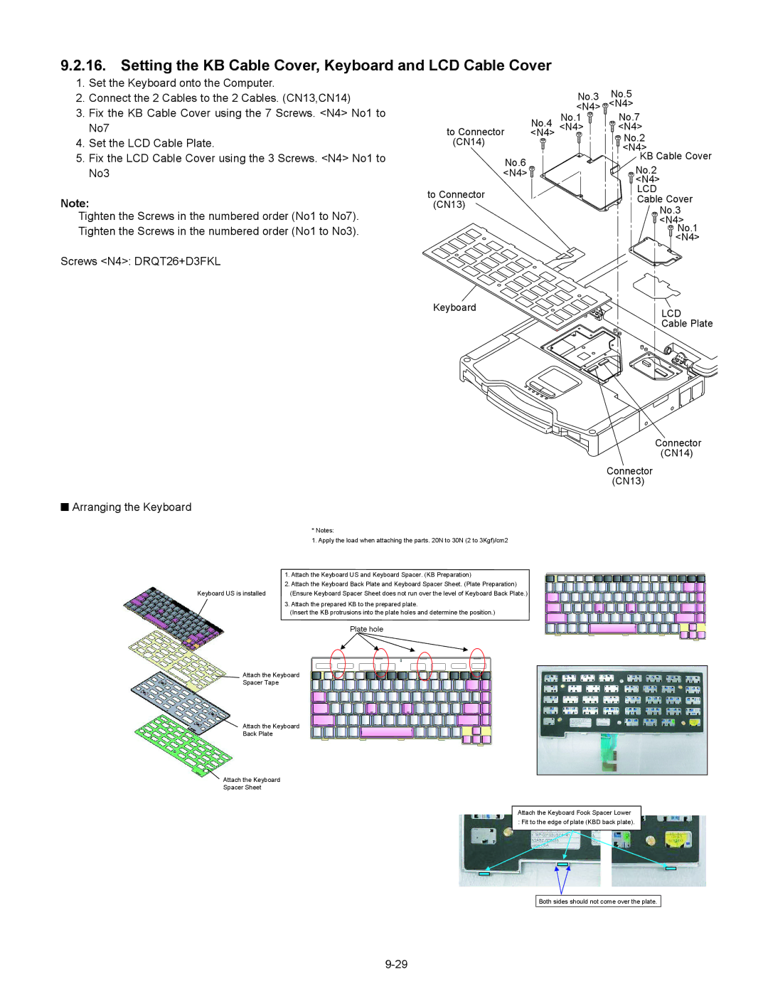
9.2.16. Setting the KB Cable Cover, Keyboard and LCD Cable Cover
1.Set the Keyboard onto the Computer.
2.Connect the 2 Cables to the 2 Cables. (CN13,CN14)
3.Fix the KB Cable Cover using the 7 Screws. <N4> No1 to No7
4.Set the LCD Cable Plate.
5.Fix the LCD Cable Cover using the 3 Screws. <N4> No1 to No3
Note:
Tighten the Screws in the numbered order (No1 to No7). Tighten the Screws in the numbered order (No1 to No3).
Screws <N4>: DRQT26+D3FKL
|
| No.3 | No.5 |
|
| <N4> | <N4> |
| No.4 | No.1 | No.7 |
to Connector | <N4> | <N4> | |
<N4> |
| No.2 | |
(CN14) |
|
| |
|
| <N4> | |
No.6 |
|
| KB Cable Cover |
|
| No.2 | |
<N4> |
|
| |
|
|
| <N4> |
to Connector |
|
| LCD |
|
| Cable Cover | |
(CN13) |
|
| |
|
| No.3 | |
|
|
| |
|
|
| <N4> |
|
|
| No.1 |
|
|
| <N4> |
Keyboard | LCD |
| |
| Cable Plate |
Connector
(CN14)
Connector
(CN13)
QArranging the Keyboard
| * Notes: |
| 1. Apply the load when attaching the parts. 20N to 30N (2 to 3Kgf)/cm2 |
| 1. Attach the Keyboard US and Keyboard Spacer. (KB Preparation) |
| 2. Attach the Keyboard Back Plate and Keyboard Spacer Sheet. (Plate Preparation) |
Keyboard US is installed | (Ensure Keyboard Spacer Sheet does not run over the level of Keyboard Back Plate.) |
| 3. Attach the prepared KB to the prepared plate. |
| (Insert the KB protrusions into the plate holes and determine the position.) |
| Plate hole |
Attach the Keyboard
Spacer Tape
Attach the Keyboard
Back Plate
Attach the Keyboard
Spacer Sheet
Attach the Keyboard Fook Spacer Lower : Fit to the edge of plate (KBD back plate).
Both sides should not come over the plate.
