HOST SOFTWARE INTERFACE
Sector Count Register
Holds the number of sectors to be sent during a Read or Write command, and the number of sectors per track during a Format command. A value of zero in this register implies a transfer of 256 sectors. A multi- sector operation decrements the Sector Count register. If an error occurs during such an operation, this register contains the remaining number of sectors to be transferred.
Sector Number Register
Holds the starting sector number for any disk operation. The register is updated as each sector is processed in a
Cylinder Number Registers
Two
Device/Head Register
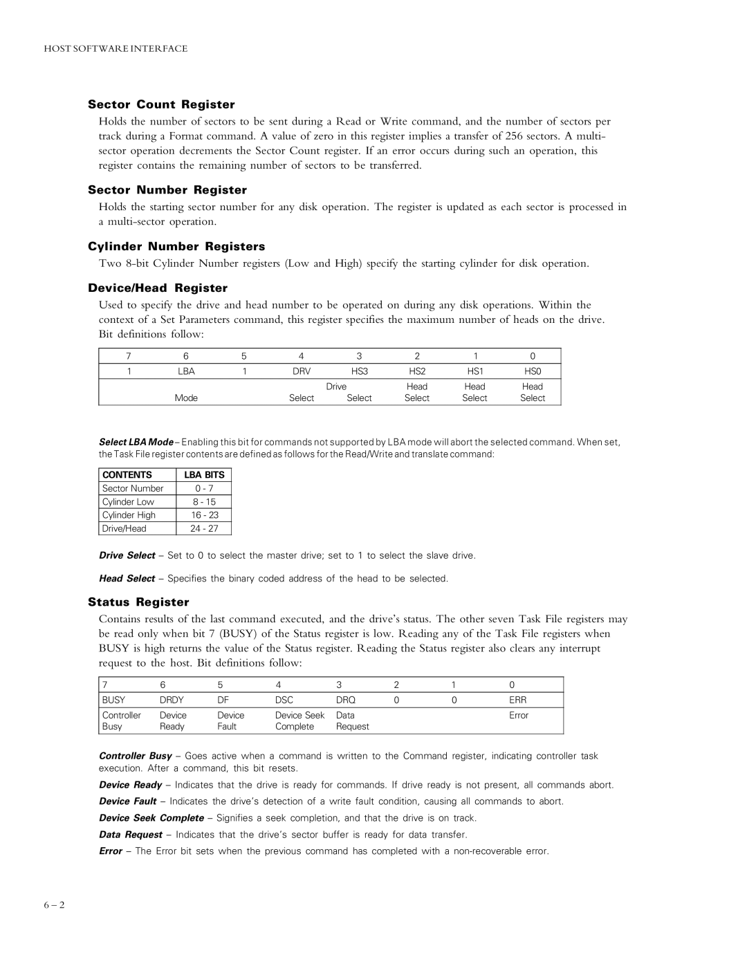
Used to specify the drive and head number to be operated on during any disk operations. Within the context of a Set Parameters command, this register specifies the maximum number of heads on the drive. Bit definitions follow:
7 | 6 | 5 | 4 | 3 | 2 | 1 | 0 |
|
|
|
|
|
|
|
|
1 | LBA | 1 | DRV | HS3 | HS2 | HS1 | HS0 |
|
|
|
|
|
|
|
|
|
|
|
| Drive | Head | Head | Head |
| Mode |
| Select | Select | Select | Select | Select |
|
|
|
|
|
|
|
|
Select LBA Mode – Enabling this bit for commands not supported by LBA mode will abort the selected command. When set, the Task File register contents are defined as follows for the Read/Write and translate command:
CONTENTS | LBA BITS | |
Sector Number | 0 | - 7 |
Cylinder Low | 8 - 15 | |
Cylinder High | 16 - 23 | |
Drive/Head | 24 | - 27 |
Drive Select – Set to 0 to select the master drive; set to 1 to select the slave drive.
Head Select – Specifies the binary coded address of the head to be selected.
Status Register
Contains results of the last command executed, and the drive’s status. The other seven Task File registers may be read only when bit 7 (BUSY) of the Status register is low. Reading any of the Task File registers when BUSY is high returns the value of the Status register. Reading the Status register also clears any interrupt request to the host. Bit definitions follow:
7 | 6 | 5 | 4 | 3 | 2 | 1 | 0 |
BUSY | DRDY | DF | DSC | DRQ | 0 | 0 | ERR |
|
|
|
|
|
|
|
|
Controller | Device | Device | Device Seek | Data |
|
| Error |
Busy | Ready | Fault | Complete | Request |
|
|
|
|
|
|
|
|
|
|
|
Controller Busy – Goes active when a command is written to the Command register, indicating controller task execution. After a command, this bit resets.
Device Ready – Indicates that the drive is ready for commands. If drive ready is not present, all commands abort. Device Fault – Indicates the drive’s detection of a write fault condition, causing all commands to abort.
Device Seek Complete – Signifies a seek completion, and that the drive is on track.
Data Request – Indicates that the drive’s sector buffer is ready for data transfer.
Error – The Error bit sets when the previous command has completed with a
6 – 2
