INTERFACE COMMANDS
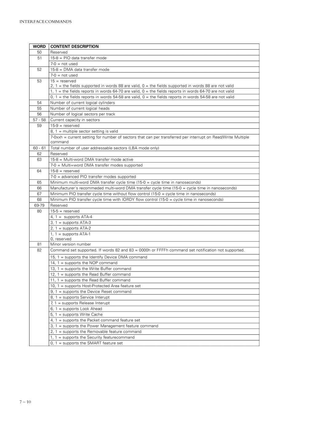
WORD | CONTENT DESCRIPTION |
50 | Reserved |
51 |
|
| |
52 | |
| |
53 | 15 = reserved |
| 2, 1 = the fields supported in words 88 are valid, 0 = the fields supported in words 88 are not valid |
| 1, 1 = the fields reports in words |
| 0, 1 = the fields reports in words |
54 | Number of current logical cylinders |
55 | Number of current logical heads |
56 | Number of logical sectors per track |
57 - 58 | Current capacity in sectors |
59 | |
| 8, 1 = multiple sector setting is valid |
| |
| command |
|
|
60 - 61 | Total number of user addressable sectors (LBA mode only) |
62 | Reserved |
63 | |
| |
64 | |
| |
65 | Minimum |
66 | Manufacturer's recommeded |
67 | Minimum PIO transfer cycle time without flow control |
68 | Minimum PIO transfer cycle time with IORDY flow control |
Reserved | |
80 | |
| 4, 1 = supports |
| 3, 1 = supports |
| 2, 1 = supports |
| 1, 1 = supports |
| 0, reserved |
81 | Minor version number |
82 | Command set supported. If words 82 and 83 = 0000h or FFFFh command set notification not supported. |
|
|
| 15, 1 = supports the Identify Device DMA command |
| 14, 1 = supports the NOP command |
| 13, 1 = supports the Write Buffer command |
| 12, 1 = supports the Read Buffer command |
| 11, 1 = supports the Read Buffer command |
| 10, 1 = supports |
| 9, 1 = supports the Device Reset command |
| 8, 1 = supports Service Interupt |
| 7, 1 = supports Release Interupt |
| 6, 1 = supports Look Ahead |
| 5, 1 = supports Write Cache |
| 4, 1 = supports the Packet command feature set |
| 3, 1 = supports the Power Management feature command |
| 2, 1 = supports the Removable feature command |
| 1, 1 = supports the Security featurecommand |
| 0, 1 = supports the SMART feature set |
7 – 10
