Switch Module Controls and LEDs
Switch Module Controls and LEDs
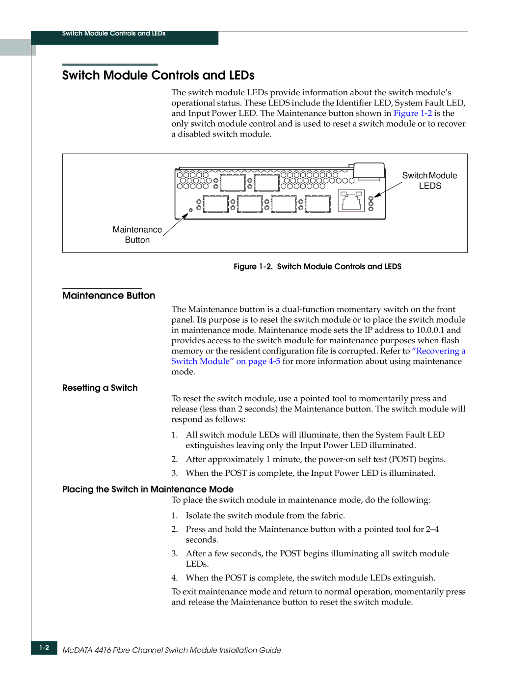
The switch module LEDs provide information about the switch module’s operational status. These LEDS include the Identifier LED, System Fault LED, and Input Power LED. The Maintenance button shown in Figure
Switch Module
LEDS
Maintenance
Button
Figure 1-2. Switch Module Controls and LEDS
Maintenance Button
The Maintenance button is a
Resetting a Switch
To reset the switch module, use a pointed tool to momentarily press and release (less than 2 seconds) the Maintenance button. The switch module will respond as follows:
1.All switch module LEDs will illuminate, then the System Fault LED extinguishes leaving only the Input Power LED illuminated.
2.After approximately 1 minute, the
3.When the POST is complete, the Input Power LED is illuminated.
Placing the Switch in Maintenance Mode
To place the switch module in maintenance mode, do the following:
1.Isolate the switch module from the fabric.
2.Press and hold the Maintenance button with a pointed tool for
3.After a few seconds, the POST begins illuminating all switch module LEDs.
4.When the POST is complete, the switch module LEDs extinguish.
To exit maintenance mode and return to normal operation, momentarily press and release the Maintenance button to reset the switch module.