Installing a Switch
When energized, the switch module responds in the following sequence:
1.The switch module LEDs (Identifier, Input Power, System Fault) illuminate followed by all port
2.After a couple seconds the System Fault LED is extinguished while the Input Power LED remains illuminated.
3.After approximately one minute, the POST executes.
4.After about another minute, the POST is complete, all LEDs are extinguished except the Input Power LED. The Input Power LED remains illuminated indicating that the switch logic circuitry is receiving DC voltage. If not, contact your authorized maintenance provider.
Connect the Management Workstation to the Switch Module
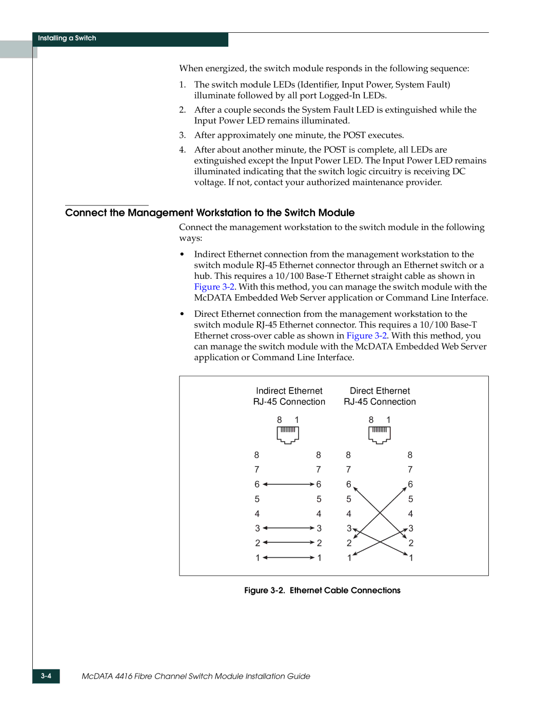
Connect the management workstation to the switch module in the following ways:
•Indirect Ethernet connection from the management workstation to the switch module
•Direct Ethernet connection from the management workstation to the switch module
Indirect Ethernet | Direct Ethernet | ||||||||||||||||
| |||||||||||||||||
8 |
| 1 |
| 8 |
| 1 | |||||||||||
|
|
|
|
|
|
|
|
|
|
|
|
|
|
|
|
|
|
|
|
|
|
|
|
|
|
|
|
|
|
|
|
|
|
|
|
|
|
|
|
|
|
|
|
|
|
|
|
|
|
|
|
|
|
8 |
|
|
| 8 | 8 |
|
| 8 | |||||||||
7 |
|
|
| 7 | 7 |
|
| 7 | |||||||||
6 |
|
|
|
| 6 | 6 |
|
| 6 | ||||||||
|
|
|
| ||||||||||||||
5 |
|
|
| 5 | 5 |
|
| 5 | |||||||||
4 |
|
|
| 4 | 4 |
|
| 4 | |||||||||
3 |
|
|
|
| 3 | 3 |
|
| 3 | ||||||||
|
|
|
| ||||||||||||||
2 |
|
|
|
| 2 | 2 |
|
| 2 | ||||||||
|
|
|
| ||||||||||||||
1 |
|
|
|
| 1 | 1 |
|
| 1 | ||||||||
|
|
|
| ||||||||||||||