Leg
Braces
Fig. 3: Tripod assembly.
Slot over Protrusion
Mounting
Thumbscrew
Fig. 4: Place slots in tray over protru- sions on leg braces.
Fine | Protrusion | |
Azimuth | ||
Star | ||
Control | ||
Knobs |
|
Mount
Locking Knob (not visible)
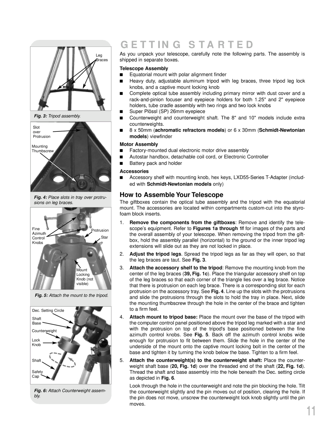
Fig. 5: Attach the mount to the tripod.
Dec. Setting Circle
Shaft
Base ![]()
![]()
Counterweight
Lock
Knob
Shaft
Safety
Cap ![]()
Fig. 6: Attach Counterweight assem- bly.
GETTING STARTED
As you unpack your telescope, carefully note the following parts. The assembly is shipped in separate boxes.
Telescope Assembly
■Equatorial mount with polar alignment finder
■Heavy duty, adjustable aluminum tripod with leg braces, three tripod leg lock knobs, and a captive mount locking knob
■Complete optical tube assembly including primary mirror with dust cover and a
■Super Plössl (SP) 26mm eyepiece
■Counterweight and counterweight shaft. The 8" and 10" models include extra counterweights.
■8 x 50mm (achromatic refractors models) or 6 x 30mm
Motor Assembly
■
■Autostar handbox, detachable coil cord, or Electronic Controller
■Battery pack and holder
Accessories
■Accessory shelf with mounting knob, hex keys,
How to Assemble Your Telescope
The giftboxes contain the optical tube assembly and the tripod with the equatorial mount. The accessories are located within compartments
1.Remove the components from the giftboxes: Remove and identify the tele- scope’s equipment. Refer to Figures 1a through 1f for images of the parts and the overall assembly of your telescope. When removing the tripod from the gift- box, hold the assembly parallel (horizontal) to the ground or the inner tripod leg extensions will slide out as they are not locked in place.
2.Adjust the tripod legs. Spread the tripod legs as far as they will open, so that the leg braces are taut. See Fig. 3.
3.Attach the accessory shelf to the tripod: Remove the mounting knob from the center of the leg braces (39, Fig. 1c). Place the triangular accessory shelf on top of the leg braces so that each corner of the triangle lies over a leg brace. Notice that there is protrusion on each leg brace. There is a corresponding slot for each protrusion on the accessory tray. See Fig. 4. Line up the slots with the protrusions and slide the protrusions through the slots to hold the tray in place. Next, slide the mounting thumbscrew through the hole in the center of the brace and tighten to a firm feel.
4.Attach mount to tripod base: Place the mount over the base of the tripod with the computer control panel positioned above the tripod leg marked with a star and with the protrusion on top of the tripod's base positioned between the fine azimuth control knobs. See Fig. 5. Back off the azimuth control knobs wide enough for protrusion to fit between them. Slide the hole in the center of the underside of the mount onto the captive mount locking bolt in the center of the base and tighten it by turning the knob below the base. Tighten to a firm feel.
5.Attach the counterweight(s) to the counterweight shaft: Place the counter- weight shaft base (20, Fig. 1d) over the threaded end of the shaft (22, Fig. 1d). Thread the shaft and base assembly into the hole beneath the Dec. setting circle as depicted in Fig. 6.
Look through the hole in the counterweight and note the pin blocking the hole. Tilt the counterweight slightly and the pin moves out of position, clearing the hole. If the pin does not move, unscrew the counterweight lock knob slightly until the pin moves.
11