ENGLISH
ADanger!
−Do not extend arbor bolt tighten- ing wrench.
−Do not tighten arbor bolt by hit- ting the assembly wrench.
10.Check the function. To do so, lower the sawhead:
−The retractable blade guard must open without touching the saw blade or any other parts.
−When returning the sawhead in the starting position, the retracta- ble blade guard must automati- cally encompass the saw blade.
−In the upper starting position of the sawhead, the safety lock must lock the retractable blade guard to prevent unintentional opening.
−Check the saw blade lock – the saw blade must turn freely.
9.2Replacing the Batteries
For battery replacement the flange laser must be removed from the saw blade. To do so, proceed as described under “Changing the Saw Blade”!
1.Place the flange laser with the metal side on a level surface; both screws must face up.
2.Loosen the screws and remove the plastic cover from the metal lower part.
3 Note:
Do not touch the switch or the laser module.
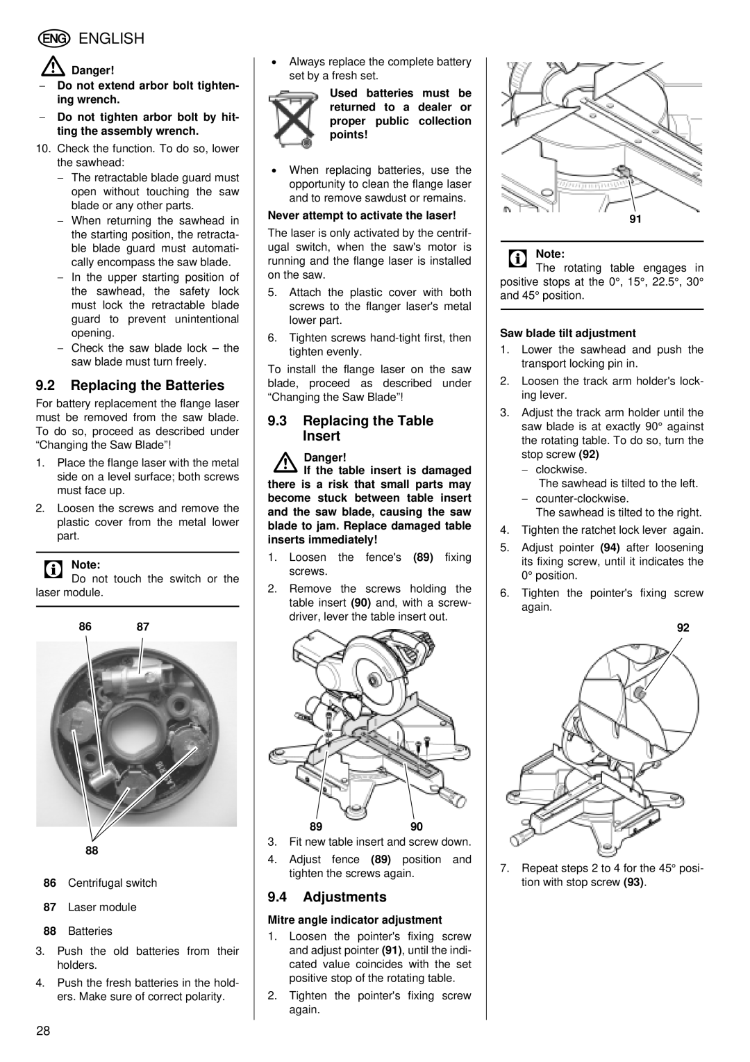
86 87
88
86Centrifugal switch
87Laser module
88Batteries
3.Push the old batteries from their holders.
4.Push the fresh batteries in the hold- ers. Make sure of correct polarity.
28
•Always replace the complete battery set by a fresh set.
Used batteries must be returned to a dealer or proper public collection points!
•When replacing batteries, use the opportunity to clean the flange laser and to remove sawdust or remains.
Never attempt to activate the laser!
The laser is only activated by the centrif- ugal switch, when the saw's motor is running and the flange laser is installed on the saw.
5.Attach the plastic cover with both screws to the flanger laser's metal lower part.
6.Tighten screws
To install the flange laser on the saw blade, proceed as described under “Changing the Saw Blade”!
9.3Replacing the Table Insert
ADanger!
If the table insert is damaged there is a risk that small parts may become stuck between table insert and the saw blade, causing the saw blade to jam. Replace damaged table inserts immediately!
1.Loosen the fence's (89) fixing screws.
2.Remove the screws holding the table insert (90) and, with a screw- driver, lever the table insert out.
8990
3.Fit new table insert and screw down.
4.Adjust fence (89) position and tighten the screws again.
9.4Adjustments
Mitre angle indicator adjustment
1.Loosen the pointer's fixing screw and adjust pointer (91), until the indi- cated value coincides with the set positive stop of the rotating table.
2.Tighten the pointer's fixing screw again.
91
3 Note:
The rotating table engages in positive stops at the 0°, 15°, 22.5°, 30° and 45° position.
Saw blade tilt adjustment
1.Lower the sawhead and push the transport locking pin in.
2.Loosen the track arm holder's lock- ing lever.
3.Adjust the track arm holder until the saw blade is at exactly 90° against the rotating table. To do so, turn the stop screw (92)
−clockwise.
The sawhead is tilted to the left.
−
The sawhead is tilted to the right.
4.Tighten the ratchet lock lever again.
5.Adjust pointer (94) after loosening its fixing screw, until it indicates the 0° position.
6.Tighten the pointer's fixing screw again.
92
7.Repeat steps 2 to 4 for the 45° posi- tion with stop screw (93).