ENGLISH
possible. With grooving no parting cut is made, but the workpiece is cut to a cer- tain depth only.
ARisk of kickback!
When grooving it is especially important no lateral pressure is applied to the saw blade. Otherwise the sawhead may be kicked up abruptly! Use a stock clamp when grooving. Avoid lateral pressure on the sawhead.
Starting position:
−Sawhead fully raised.
−Sawhead tilted to desired angle against the workpiece's surface and locked.
−Rotating table locked in desired position.
−Lock screw of the track arm loos- ened.
−Track arm not extended.
Cutting the workpiece:
1.Adjust cutting depth limiter (67) to desired cutting depth and secure setting with locking nut.
67
2.Hold workpiece against the fence.
3 Note:For the groove to be cut at the desired depth across the whole work- piece width, a suitable spacer strip needs to be attached to the fence.
3.Push the safety lock to the side and press and hold the ON/OFF switch.
4.Slowly swing the sawhead fully down, holding the handle firmly.
A Caution!
When sawing exert only mod- erate downward pressure on the saw- head, so the motor speed is not reduced too much, otherwise the motor may be overloaded and dam- aged.
5.When sawing, pull sawhead forward (towards the operator).
6.Groove workpiece in a single pass.
7.Release the ON/OFF switch and let the sawhead slowly return to its upper starting position.
8.Return the sawhead to the rear posi- tion.
8.6Support
1.Loosen thumb screw (68).
6968
2.Slide support, depending on the workpiece's length, on the work sup- port (69) to the left, as far as neces- sary.
3.Lock support with the thumb screw (68).
Adjusting the support
The support's rear stop face must be in line with the saw table's fence.
For this, the position of the support's stop face can be adjusted:
1.Loosen both screws (70).
70
71
2.Bring the rear stop face (71) in line with the fence.
3.Tighten both screws (70).
8.7Stock Stop
1.Loosen thumb screw (72).
7273
2.Move stock stop on the work sup- port (73), as required by the work- piece length.
3.Tighten thumb screw (72).
If not required, swing stock stop to the rear, out of the way.
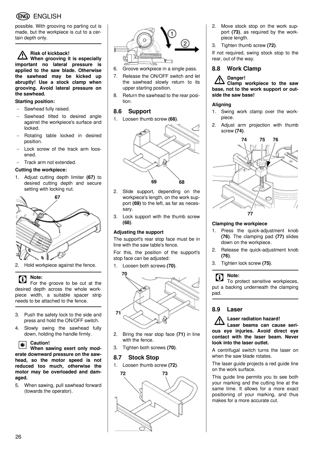
8.8Work Clamp
ADanger!
Clamp workpiece to the saw base, not to the work support or out- side the saw base!
Aligning
1.Swing work clamp over the work- piece.
2.Adjust arm projection with thumb screw (74).
74 75 76
77
Clamping the workpiece
1.Press the
2.Release the
3.Tighten lock screw (75).
3 Note:To protect sensitive workpieces, put a backing underneath the clamping pad.
8.9Laser
ALaser radiation hazard!
Laser beams can cause seri- ous eye injuries. Avoid direct eye contact with the laser beam. Never look into the laser outlet.
A centrifugal switch turns the laser on when the saw blade rotates.
The laser guide projects a red guide line on the work surface.
This guide line permits you to see both your marking and the cutting line at the same time. It allows for a more exact positioning of your marking, and thus makes for a more accurate cut.
26