The RAIDBank5 interface components
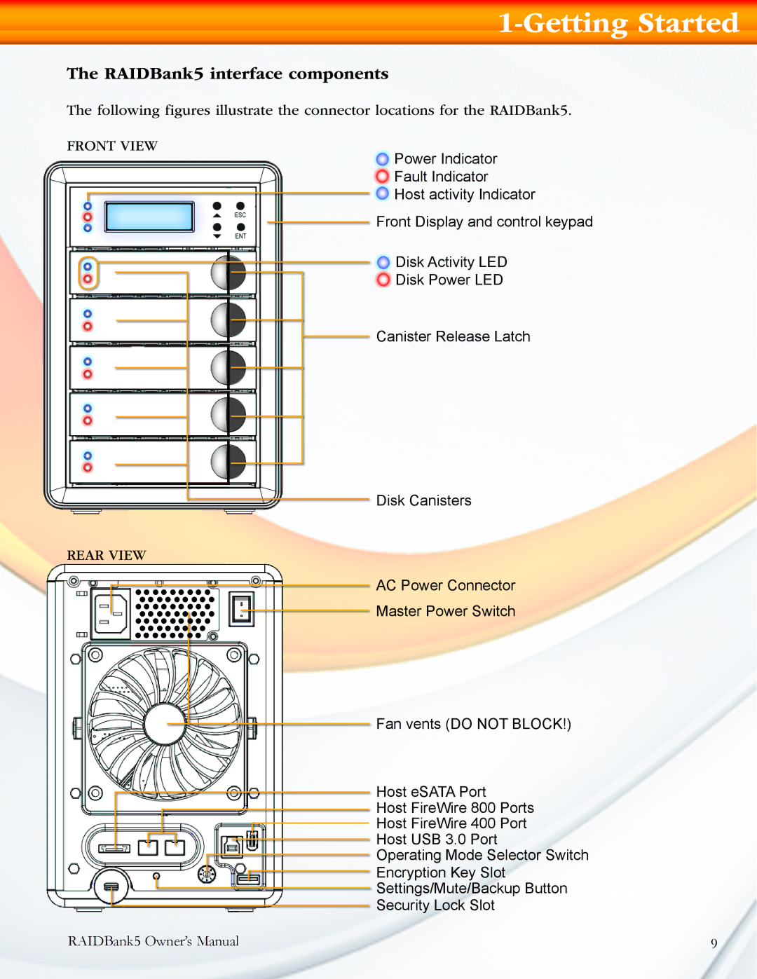
The following figures illustrate the connector locations for the RAIDBank5.
FRONT VIEW
Power Indicator
Fault Indicator
Host activity Indicator
Front Display and control keypad
Disk Activity LED
Disk Power LED
Canister Release Latch
Disk Canisters
REAR VIEW
AC Power Connector
Master Power Switch
Fan vents (DO NOT BLOCK!)
Host eSATA Port
Host FireWire 800 Ports
Host FireWire 400 Port
Host USB 3.0 Port
Operating Mode Selector Switch
Encryption Key Slot
Settings/Mute/Backup Button
Security Lock Slot RAIDBank5 Owner’s Manual
1-Getting Started
9