Installation
Preparing the Site
Select the site that meets the following requirements:
Characteristic | Requirement |
Temperature | 32 to 104˚F (0 to 40˚C) |
|
|
Humidity | Maximum relative humidity of 90%, |
|
|
Condition | At least 1.8 meters (6 feet) to the nearest source of electromagnetic noise |
|
|
Ventilation | Minimum 3 inches (0.25 feet) of clearance around the ventilation openings |
|
|
Power Outlet | Within 1.8 meters (6 feet) to the switch |
|
|
Table 2: SP616DB / SP624DB Operating Requirements
Settling the Switch
zMounted to 19-inch standard rack
Locate the accessories provided in the product package. Use the
Step 1: Attach the brackets to each side of the chassis.
Step 2: Apply the screws to each side and secure them tightly.
Step 3: Carefully position the switch into the rack.
Step 4: Align the brackets to the side holes on the rack and use rack screws to secure the chassis with the rack.
Step 5: Proceed to the “Connecting to Power” section.
zDesktop or any flat surface
The switch can sit on desktop or any flat surface with adequate space and ventilation. If you want to place it onto a shelf, make sure the shelf can withstand the weight of the switch. Step 1: Simply put the switch on the desired place.
Step 2: Ensure the switch receives good ventilation.
Step 3: Proceed to the “Connecting to Power” section.
Installing the Module (optional)
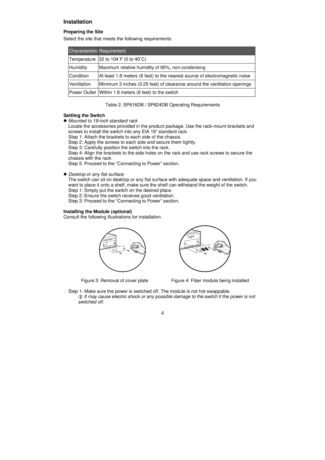
Consult the following illustrations for installation.
Figure 3: Removal of cover plate | Figure 4: Fiber module being installed |
Step 1: Make sure the power is switched off. The module is not
It may cause electric shock or any possible damage to the switch if the power is not switched off.
4
