External Wiring
SECTION IX - External Wiring | areas of draft, lighting fixtures and fire- | |
Installation Compliance | places. | |
4. Set the thermostat anticipator (if applica- | ||
| ||
All field wiring made during installation must | ble) as follows: | |
- Set for 0.2 amps when wired directly to | ||
comply with: | ||
- National Electrical Code NFPA 70 and | the Room Thermostat | |
- Set to match the total electrical power | ||
any other national, state, provincial or | ||
local codes or requirements. | requirements of the connected devices | |
- In Canada, CSA C22.1 Canadian | when wired to zone relays or other | |
devices. Refer to the relay manufactur- | ||
Electrical Code Part 1, and any other | ||
ers’ specifications and the thermostat | ||
local codes. | ||
instructions for additional information | ||
| ||
Line Voltage Connections | on the anticipator setting. | |
|
1.Connect 120 VAC power wire to the line voltage leads located behind the front con- trol panel.
2.Route the incoming 120 VAC power wire through the right side jacket panel.
3.Use the wire nuts provided to ensure a tight and secure connection.
4.The unit is provided with a service switch, check local code requirements for compli- ance.
NOTICE
If local electrical codes or conditions require an additional service switch, the installer must provide and install a fused disconnect or 15 amp (minimum) service switch.
Thermostat Wiring
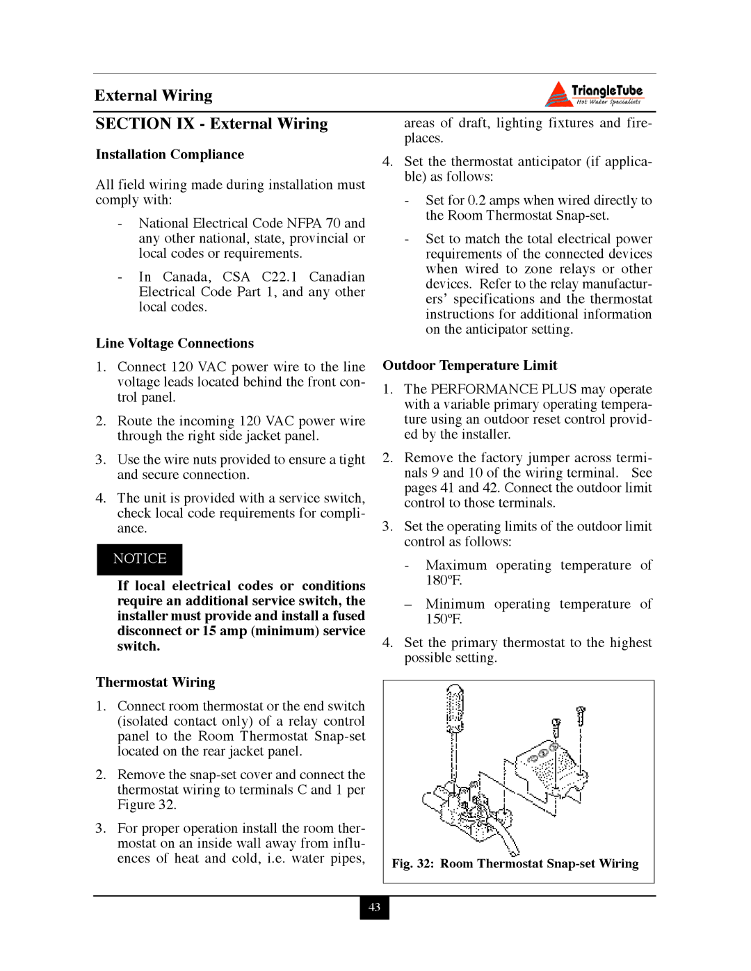
1.Connect room thermostat or the end switch (isolated contact only) of a relay control panel to the Room Thermostat
2.Remove the
3.For proper operation install the room ther- mostat on an inside wall away from influ- ences of heat and cold, i.e. water pipes,
Outdoor Temperature Limit
1.The PERFORMANCE PLUS may operate with a variable primary operating tempera- ture using an outdoor reset control provid- ed by the installer.
2.Remove the factory jumper across termi- nals 9 and 10 of the wiring terminal. See pages 41 and 42. Connect the outdoor limit control to those terminals.
3.Set the operating limits of the outdoor limit control as follows:
-Maximum operating temperature of 180ºF.
–Minimum operating temperature of 150ºF.
4.Set the primary thermostat to the highest possible setting.
Fig. 32: Room Thermostat Snap-set Wiring
43