Gas Piping
NATURAL GAS
Pipe Sizing - Natural Gas
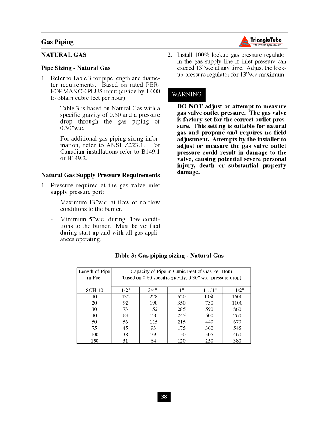
1.Refer to Table 3 for pipe length and diame- ter requirements. Based on rated PER- FORMANCE PLUS input (divide by 1,000 to obtain cubic feet per hour).
-Table 3 is based on Natural Gas with a specific gravity of 0.60 and a pressure drop through the gas piping of 0.30”w.c..
-For additional gas piping sizing infor- mation, refer to ANSI Z223.1. For Canadian installations refer to B149.1 or B149.2.
Natural Gas Supply Pressure Requirements
1.Pressure required at the gas valve inlet supply pressure port:
-Maximum 13”w.c. at flow or no flow conditions to the burner.
-Minimum 5”w.c. during flow condi- tions to the burner. Must be verified during start up and with all gas appli- ances operating.
2.Install 100% lockup gas pressure regulator in the gas supply line if inlet pressure can exceed 13”w.c at any time. Adjust the lock- up pressure regulator for 13”w.c maximum.
WARNING
DO NOT adjust or attempt to measure gas valve outlet pressure. The gas valve is
Table 3: Gas piping sizing - Natural Gas
Length of Pipe |
| Capacity of Pipe in Cubic Feet of Gas Per Hour | ||||
in Feet | (based on 0.60 specific gravity, 0.30" w.c. pressure drop) | |||||
SCH 40 |
|
|
|
|
| |
1/2" |
| 3/4" | 1" | |||
10 | 132 |
| 278 | 520 | 1050 | 1600 |
20 | 92 |
| 190 | 350 | 730 | 1100 |
30 | 73 |
| 152 | 285 | 590 | 860 |
40 | 63 |
| 130 | 245 | 500 | 760 |
50 | 56 |
| 115 | 215 | 440 | 670 |
75 | 45 |
| 93 | 175 | 360 | 545 |
100 | 38 |
| 79 | 150 | 305 | 460 |
150 | 31 |
| 64 | 120 | 250 | 380 |
38