Net Safety Monitoring Inc.
STEP 4 — OPERATE
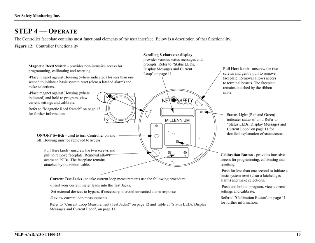
The Controller faceplate contains most functional elements of the user interface. Below is a description of that functionality.
Figure 12: Controller Functionality
Magnetic Reed Switch - provides
Refer to "Magnetic Reed Switch" on page 12 for further information.
ON/OFF Switch - used to turn Controller on and off. Housing must be removed to access.
Pull Here knob - unscrew the two screws and pull to remove faceplate. Removal allows access to PCBs. The faceplate remains attached by the ribbon cable.
Scrolling 8-character display -
provides various status messages and prompts. Refer to "Status LEDs, Display Messages and Current Loop" on page 11.
|
|
|
| Pull |
|
|
|
| Here |
C |
|
|
|
|
al/ |
|
|
| Status |
R | et |
| ||
Mag |
|
| ||
| es |
|
| |
On Si | n | et |
| Red |
|
| |||
de |
| |||
|
|
|
| Slow Flash: |
|
|
| Calibration/Setup | Gas present |
|
|
| Cal or Fault | |
|
|
|
| Flast flash : |
| On | Solid: | ||
| magnet until countdown | Overrange | ||
|
|
| is zero (~10 sec) | Green |
|
|
| ||
|
|
| display | Short Blips: |
|
|
| Normal | |
|
|
|
| |
|
|
|
| operation. |
| Off |
| No gas | |
|
| present | ||
Power
Current O/P Check
Pull
Connect current probes to meter jacks and read mA output
Pull Here knob - unscrew the two screws and gently pull to remove faceplate. Removal allows access to terminal boards. The faceplate remains attached by the ribbon cable.
Status Light (Red and Green) - indicates status of unit. Refer to "Status LEDs, Display Messages and Current Loop" on page 11 for detailed explanation of states/status.
Calibration Button - provides intrusive access for programming, calibrating and resetting.
Current Test Jacks - to take current loop measurements use the following procedure:
Refer to "Current Loop Measurement (Test Jacks)" on page 12 and Table 2, "Status LEDs, Display Messages and Current Loop", on page 11.
Refer to "Calibration Button" on page 11 for further information.
10 |