Net Safety Monitoring Inc
STEP 1 — PLAN
LOCATE CONTROLLER/SENSOR
Prior to the installation process, a location plan for placing the Controller and Sensor should be developed. Although there are no absolute rules for determining the quantity and location of a sensor or controller, the following points should be considered when planning the installation.
•Locate the Controller where it will be accessible and visible.
•Oxygen deficiency can be caused by O2 consumption from such activities as chemical reactions or combustion and/or displacement by other gases.
•Use redundant systems to enhance protection and reliability.
•Consider air movement patterns within the facility.
•Seek advice from experts knowledgeable about the primary gas to be detected.
•Use common sense and refer to various regulatory publications that discuss general guidelines for your industry.
The two most common installation options are as follows.
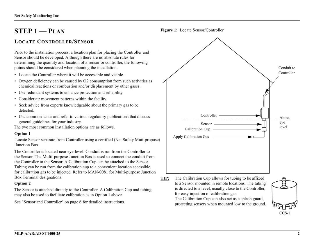
Figure 1: Locate Sensor/Controller
Conduit to
Controller
Controller | About | |
| ||
Sensor | eye | |
level | ||
Calibration Cup | ||
|
Option 1
Locate Sensor separate from Controller using a certified (Net Safety
The Controller is located near |
|
the Sensor. The |
|
the Controller to the Sensor. A Calibration Cup can be attached to the Sensor. |
|
Tubing can be run from the calibration cup to a convenient location accessible |
|
for calibration gas to be injected. Refer to |
|
Box Terminal designations. | TIP: |
Option 2 |
|
The Sensor is attached directly to the Controller. A Calibration Cup and tubing |
|
may also be used to facilitate calibration as in Option 1 above. |
|
See "Sensor and Controller" on page 6 for detailed instructions. |
|
Apply Calibration Gas
The Calibration Cup allows for tubing to be affixed to a Sensor mounted in remote locations. The tubing is directed to a level, usually close to the Controller, for easy injection of calibration gas.
The Calibration Cup can also act as a splash guard, protecting sensors when mounted low to the ground.
2 |