5-7. Connecting To Weld Output Terminals
! Stop engine.
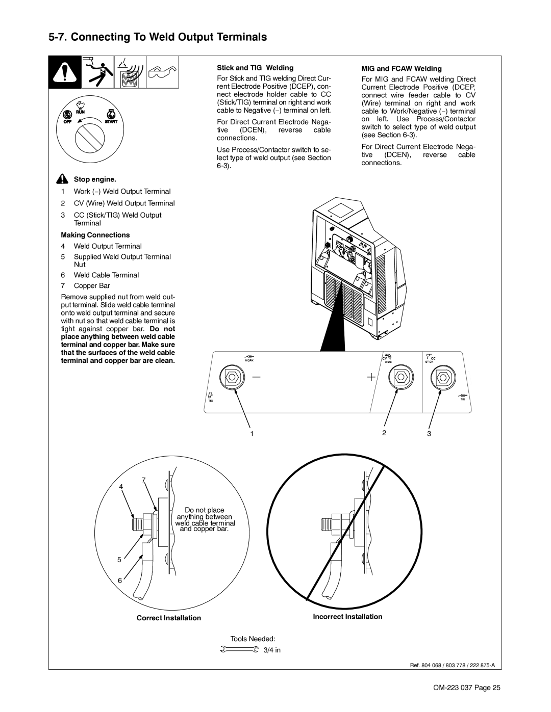
1Work (−) Weld Output Terminal
2CV (Wire) Weld Output Terminal
3CC (Stick/TIG) Weld Output Terminal
Making Connections
4Weld Output Terminal
5Supplied Weld Output Terminal Nut
6Weld Cable Terminal
7Copper Bar
Remove supplied nut from weld out- put terminal. Slide weld cable terminal onto weld output terminal and secure with nut so that weld cable terminal is tight against copper bar. Do not place anything between weld cable terminal and copper bar. Make sure that the surfaces of the weld cable terminal and copper bar are clean.
Stick and TIG Welding
For Stick and TIG welding Direct Cur- rent Electrode Positive (DCEP), con- nect electrode holder cable to CC (Stick/TIG) terminal on right and work cable to Negative (−) terminal on left.
For Direct Current Electrode Nega- tive (DCEN), reverse cable connections.
Use Process/Contactor switch to se- lect type of weld output (see Section
MIG and FCAW Welding
For MIG and FCAW welding Direct Current Electrode Positive (DCEP, connect wire feeder cable to CV (Wire) terminal on right and work cable to Work/Negative (−) terminal on left. Use Process/Contactor switch to select type of weld output (see Section
For Direct Current Electrode Nega- tive (DCEN), reverse cable connections.
4
5
6
1 | 2 | 3 |
7
Do not place
anything between weld cable terminal and copper bar.
Correct Installation | Incorrect Installation |
Tools Needed: 3/4 in
Ref. 804 068 / 803 778 / 222