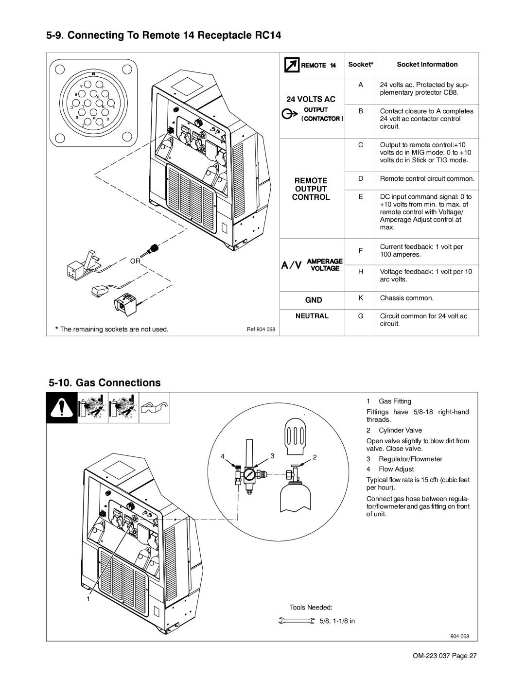
5-9. Connecting To Remote 14 Receptacle RC14
![]()
![]() OR
OR
* The remaining sockets are not used.
Ref 804 068
| Socket* | Socket Information |
| A | 24 volts ac. Protected by sup- |
24 VOLTS AC |
| plementary protector CB8. |
|
| |
| B | Contact closure to A completes |
|
| 24 volt ac contactor control |
|
| circuit. |
| C | Output to remote control:+10 |
|
| volts dc in MIG mode; 0 to +10 |
|
| volts dc in Stick or TIG mode. |
REMOTE | D | Remote control circuit common. |
OUTPUT | E | DC input command signal: 0 to |
CONTROL | ||
|
| +10 volts from min. to max. of |
|
| remote control with Voltage/ |
|
| Amperage Adjust control at |
|
| max. |
| F | Current feedback: 1 volt per |
| 100 amperes. | |
|
| |
| H | Voltage feedback: 1 volt per 10 |
|
| arc volts. |
GND | K | Chassis common. |
NEUTRAL | G | Circuit common for 24 volt ac |
|
| circuit. |
5-10. Gas Connections
4 | 3 | 2 |
1
Tools Needed:
5/8,
1 Gas Fitting
Fittings have
2 Cylinder Valve
Open valve slightly to blow dirt from valve. Close valve.
3Regulator/Flowmeter
4Flow Adjust
Typical flow rate is 15 cfh (cubic feet per hour).
Connect gas hose between regula- tor/flowmeter and gas fitting on front of unit.
804 068