8-10. Optional Voltmeter/Ammeter Help Displays
1
![]()
![]() HL.P
HL.P
2
 HL.P
HL.P
3
![]() HL.P
HL.P
4
![]() HL.P
HL.P
5
![]() HL.P
HL.P
6
![]() HL.P
HL.P
20![]()
21![]()
22![]()
23![]()
24![]()
25![]()
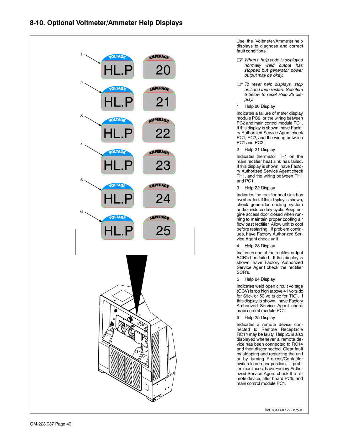
Use the Voltmeter/Ammeter help displays to diagnose and correct fault conditions.
.When a help code is displayed
normally weld output has stopped but generator power output may be okay.
.To reset help displays, stop unit and then restart. See item 6 below to reset Help 25 dis- play.
1 Help 20 Display
Indicates a failure of meter display module PC2, or the wiring between PC2 and main control module PC1. If this display is shown, have Facto- ry Authorized Service Agent check PC1, PC2, and the wiring between PC1 and PC2.
2 Help 21 Display
Indicates thermistor TH1 on the main rectifier heat sink has failed. If this display is shown, have Facto- ry Authorized Service Agent check TH1, and the wiring between TH1 and PC1.
3 Help 22 Display
Indicates the rectifier heat sink has overheated. If this display is shown, check generator cooling system and/or reduce duty cycle. Keep en- gine access door closed when run- ning to maintain proper cooling air flow past rectifier. Allow unit to cool before restarting. If problem contin- ues, have Factory Authorized Ser- vice Agent check unit.
4 Help 23 Display
Indicates one of the rectifier output SCR’s has failed. If this display is shown, have Factory Authorized Service Agent check the rectifier SCR’s.
5 Help 24 Display
Indicates weld open circuit voltage (OCV) is too high (above 41 volts dc for Stick or 50 volts dc for TIG). If this display is shown, have Factory Authorized Service Agent check main control module PC1.
6 Help 25 Display
Indicates a remote device con- nected to Remote Receptacle RC14 may be faulty. Help 25 is also displayed whenever a remote de- vice has been connected to RC14 and then disconnected. Clear fault by stopping and restarting the unit or by turning Process/Contactor switch to another position. If prob- lem continues, have Factory Autho- rized Service Agent check the re- mote device, filter board PC6, and main control module PC1.
Ref. 804 068 / 222