File Engine Drive
OM-4421215 075N
Processes
Description
From Miller to You
Table of Contents
− Maintenance & Troubleshooting
Directives
Standards
Decrot9/06
Decrotsound6/05
Manufacturer European Contact Notified Body
Arc Welding Hazards
Symbol Usage
Engine Hazards
Compressed Air Hazards
Radiation can cause interference
Principal Safety Standards
California Proposition 65 Warnings
EMF Information
LES Fumées ET LES GAZ peuvent être dangereux
Signification des symboles
− Consignes DE Sécurité − Lire Avant Utilisation
UN Choc Électrique peut tuer
LE Bruit peut affecter l’ouïe
LE Soudage peut provoquer un in- cendie ou une explosion
DES Particules Volantes peuvent blesser les yeux
DES Pièces Chaudes peuvent provoquer des brûlures graves
LES Étincelles Volantes risquent de provoquer des blessures
’AIR Comprimé peut provoquer des blessures
’EMPLOI Excessif peut
LE Surchauffement peut endom- mager le moteur électrique
Boulevard, Rexdale, Ontario, Canada M9W 1R3 téléphone
LE Soudage À L’ARC risque de provoquer des interférences
Pour les moteurs à essence
Pour les moteurs diesel
− Definitions
− 50 h Std
Std
Manufacturer’s Rating Labels
CC Models CC/CV Models CC Export Models
OM-4421
Symbols And Definitions
− Specifications
Weld, Power, And Engine Specifications
Dimensions, Weights, And Operating Angles
Volt-Ampere Curves For CC Models
Volt-Ampere Curves For CC/CV Models
Stick Mode
MIG Mode
TIG Mode
Duty Cycle And Overheating
Curve shows typical fuel use under weld or power loads
Exceeding duty cycle can damage unit and void warranty
Fuel Consumption
15 kVA/kW Three-Phase AC Output No Weld Load
AC Generator Power Curve
Optional Three-Phase Generator Curves
12 kVA/kW Single-Phase AC Output No Weld Load
Grounding1
− Installation
Installing Welding Generator
Location/Airflow Clearance
Using Lifting Eye
To Bolt Unit In Place
Mounting Welding Generator
Supporting The Unit
Mounting Surface
Installing Exhaust Pipe
Tools Needed 1/2
Stop engine and let cool
For 30 Minutes
Activating The Dry Charge Battery If Applicable
Connecting The Battery
Do not overfill battery cells
Hot Full Cold Full
Coolant Recovery Tank
Engine Prestart Checks
Full Capacity Engine 9.5 qt 9.01L Diesel
Stop engine
Connecting To Weld Output Terminals
Stick and TIG Welding
MIG and Fcaw Welding
Stop engine before
Selecting Weld Cable Sizes
150 ft 200 ft 250 ft
350 ft 400 ft 45 m 60 m 70 m 90 m 105 m 120 m
Socket
Connecting To Remote 14 Receptacle RC14 On CC/CV Models
Front Panel Controls For CC Models See Section
− Operating Welding Generator − CC Models
Engine Gauges And Meters
To Start Do not use ether. Using ether voids warranty
Do not switch under load
Engine Starting Controls
Remote Amperage Control On CC Models Optional
Weld Control/Arc Condition Information Label
Example Combination Remote Amperage Control Stick
OM-4421
Front Panel Controls For CC/CV Models See Section
− Operating Welding Generator − CC/CV Models
Use switch to select weld amperage range
Voltage/Amperage Adjust Switch And Remote 14 Receptacle
14 AC/DC Voltmeter Optional
Process/Contactor Switch Settings
Process/Contactor Switch On CC/CV Models
Example Combination Remote Amperage Control TIG
Remote Voltage/Amperage Control On CC/CV Models Optional
Volt And 240 Volt Receptacles
− Operating Auxiliary Equipment
Single-Phase Generator Power Three-Phase Power Connection
Rear Of Panel
Close panel opening if no connections are made to generator
Optional Generator Power Receptacles
240 V 15 a AC South African Receptacle RC1
Supplementary Protector CB2 Supplementary Protector CB3
Maintenance Label
− Maintenance & Troubleshooting
Routine Maintenance
Checking Generator Brushes
Do not clean housing with air hose
Servicing Air Cleaner
By the warranty
To clean air filter
Inspecting And Cleaning Optional Spark Arrestor Muffler
Stop engine and let cool. Reinstall cleanout plug
Tools Needed 3/8
Standard Model Idle Speed Ad- justment
Adjusting Engine Speed
Weld/Power Speed Adjustment
Engine Speed No Load
Servicing Fuel And Lubrication Systems
Overload Protection
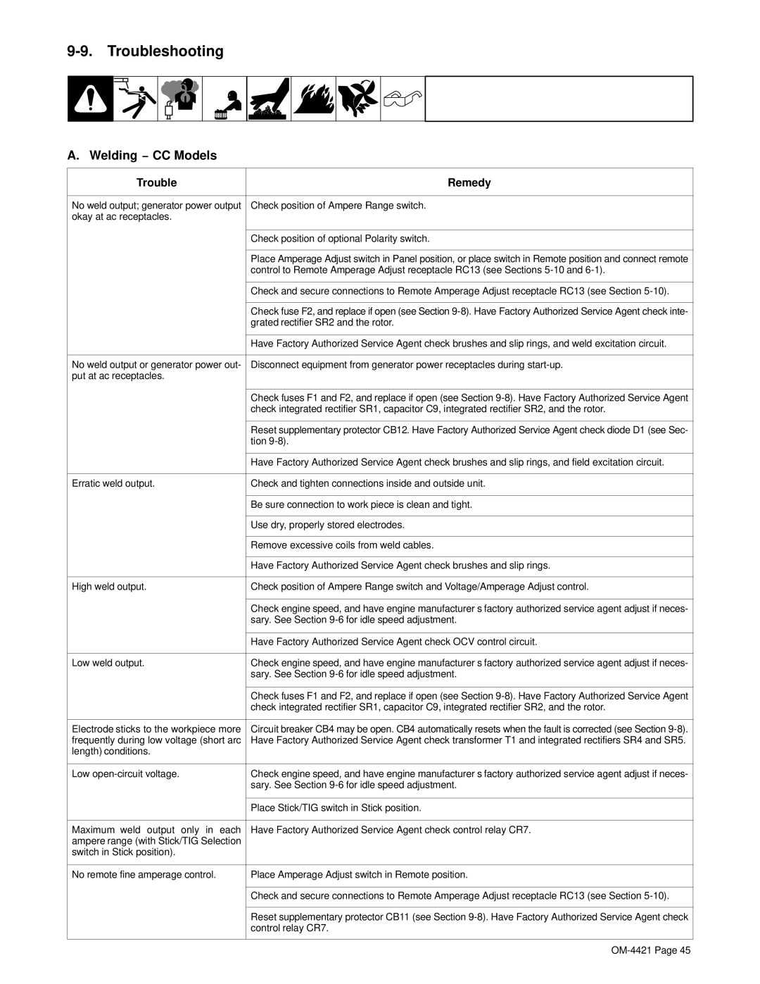
Welding − CC Models
Troubleshooting
Welding − CC/CV Models
Optional Three-Phase Generator Power CC/CV Models Only
Standard Generator Power
Engine
OM-4421
Circuit Diagram For CC Welding Generator
− Electrical Diagrams
223 522-B
Circuit Diagram For CC/CV Welding Generator
223 523-B
− RUN-IN Procedure
Wetstacking
Welding Generator
From flammables Do not Perform
Run-In Procedure Using Load Bank
Procedure at less than
Stop engine Do not touch hot exhaust
Do not perform run-in
Run-In Procedure Using Resistance Grid
Bank/grid
From flammables
− Generator Power Guidelines
Selecting Equipment
Grounding Generator To Truck Or Trailer Frame
Amperes x Volts = Watts
Grounding When Supplying Building Systems
How Much Power Does Equipment Require?
Earth ground if supplying
Farm/Home Equipment Rating Starting Watts Running Watts
Approximate Power Requirements For Industrial Motors
Approximate Power Requirements For Farm/Home Equipment
Industrial Motors Rating Starting Watts Running Watts
Contractor Rating Starting Watts Running Watts
Approximate Power Requirements For Contractor Equipment
KVA/HP x HP x 1000 = Starting Amperage
Power Required To Start Motor
How Much Power Can Generator Supply?
Single-Phase Induction Motor Starting Requirements
Typical Connections To Supply Standby Power
Current Load Watts Amperes
Selecting Extension Cord Use Shortest Cord Possible
− Parts List
93 −6 105 104 100 101 102 103
Main Assembly
010
Figures 13-2
Figures 13-4
Control Box Assembly − CC Models
087
Control Box Assembly − CC/CV Models -1Item
Control Box Assembly − CC/CV Models
TD1 214
3634
Panel, Front w/Components − CC Models
Panel, Front w/Components − CC Models -1Item
40 39
Panel, Front w/Components − CC/CV Models
Panel, Front w/Components − CC/CV Models -1Item
170
Generator -1Item
Generator
602 SCREW, .312−18x .75 hexwhd.66d stl pld slffmg tap−rw 601
Main Rectifier Assembly
Wiring Harnesses
PLG4
Harness, receptacle auxiliary power export models includes
Page
Service
Your distributor also gives
Support
Your distributor and/or equipment manufacturer’s
To locate a Distributor or Service Agency visit
Miller Electric Mfg. Co
For assistance in filing or settling claims, contact