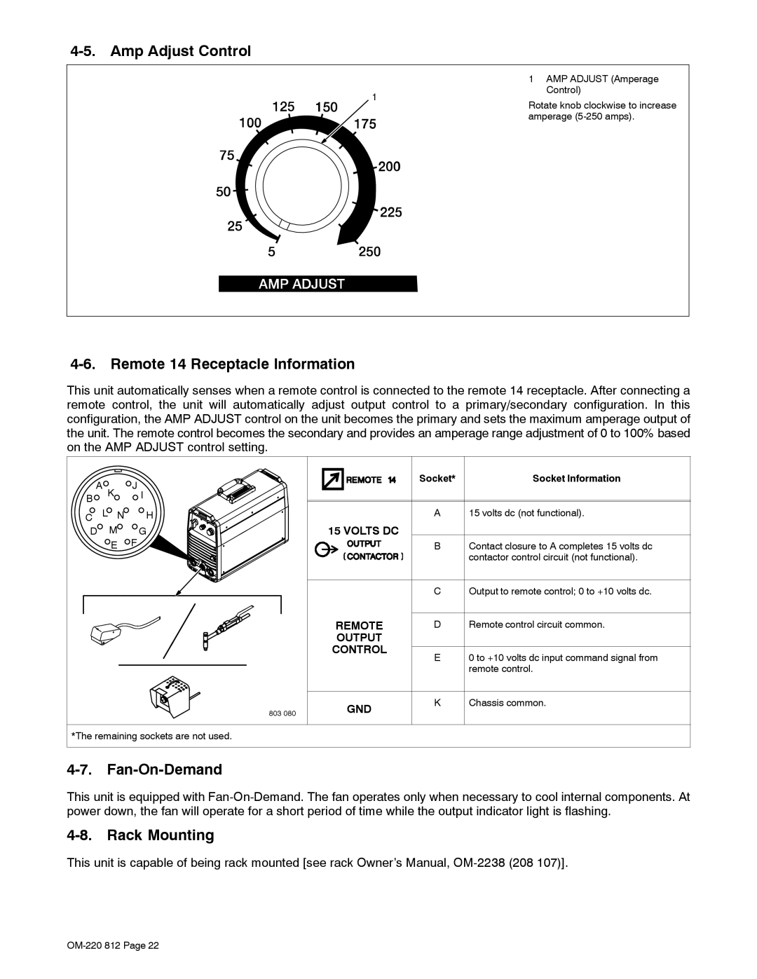
4-5. Amp Adjust Control
| 1 AMP ADJUST (Amperage | |
1 | Control) | |
Rotate knob clockwise to increase | ||
| ||
| amperage |
4-6. Remote 14 Receptacle Information
This unit automatically senses when a remote control is connected to the remote 14 receptacle. After connecting a remote control, the unit will automatically adjust output control to a primary/secondary configuration. In this configuration, the AMP ADJUST control on the unit becomes the primary and sets the maximum amperage output of the unit. The remote control becomes the secondary and provides an amperage range adjustment of 0 to 100% based on the AMP ADJUST control setting.
A K | J I | |
B |
|
|
C | L N | H |
D | M | G |
| E | F |
803 080
| Socket* | Socket Information |
| A | 15 volts dc (not functional). |
15 VOLTS DC |
|
|
| B | Contact closure to A completes 15 volts dc |
|
| contactor control circuit (not functional). |
| C | Output to remote control; 0 to +10 volts dc. |
REMOTE | D | Remote control circuit common. |
OUTPUT |
|
|
CONTROL | E | 0 to +10 volts dc input command signal from |
| ||
|
| remote control. |
GND | K | Chassis common. |
|
|
*The remaining sockets are not used.
4-7. Fan-On-Demand
This unit is equipped with
4-8. Rack Mounting
This unit is capable of being rack mounted [see rack Owner’s Manual,
