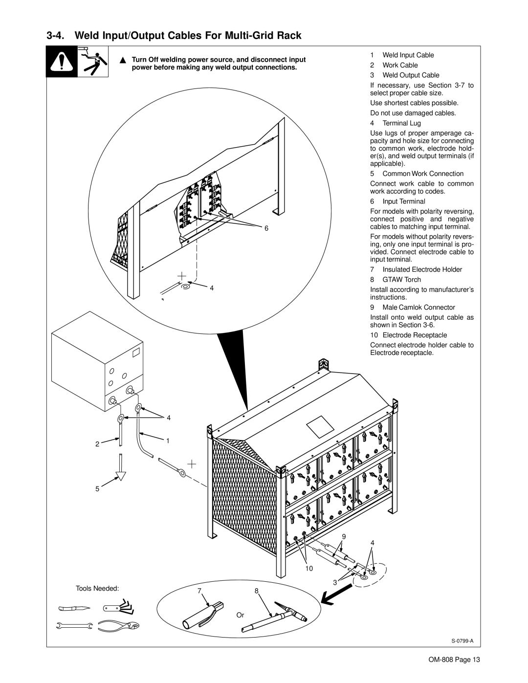
3-4. Weld Input/Output Cables For Multi-Grid Rack
2
5
Tools Needed:
Y Turn Off welding power source, and disconnect input | 1 | Weld Input Cable | |
2 | Work Cable | ||
power before making any weld output connections. | |||
| 3 | Weld Output Cable | |
| If necessary, use Section | ||
| select proper cable size. | ||
| Use shortest cables possible. | ||
| Do not use damaged cables. | ||
| 4 | Terminal Lug | |
| Use lugs of proper amperage ca- | ||
| pacity and hole size for connecting | ||
| to common work, electrode hold- | ||
| er(s), and weld output terminals (if | ||
| applicable). | ||
| 5 | Common Work Connection | |
| Connect work cable to common | ||
| work according to codes. | ||
| 6 | Input Terminal | |
| For models with polarity reversing, | ||
| connect positive and negative | ||
6 | cables to matching input terminal. | ||
| For models without polarity revers- | ||
| ing, only one input terminal is pro- | ||
| vided. Connect electrode cable to | ||
| input terminal. | ||
| 7 | Insulated Electrode Holder | |
| 8 | GTAW Torch | |
4 | Install according to manufacturer’s | ||
| instructions. | ||
| 9 | Male Camlok Connector | |
| Install onto weld output cable as | ||
| shown in Section | ||
| 10 | Electrode Receptacle | |
| Connect electrode holder cable to | ||
| Electrode receptacle. | ||
![]() 4
4
1
9
4
10
3
78
Or
