2
Do not touch live electrical parts.
Do not touch electrode holders of opposite polarity at the same time. Separate electrode holders of opposite polarity to prevent contact. Consult ANSI Z49.1 for common grounding safe practices.
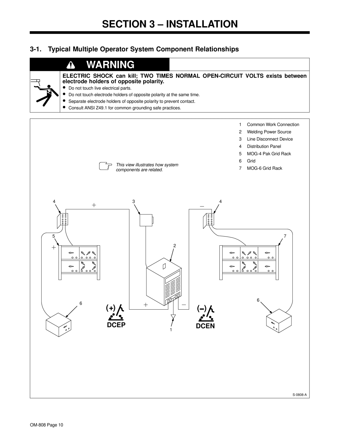
This view illustrates how system components are related.
SECTION 3 – INSTALLATION
3-1. Typical Multiple Operator System Component Relationships
WARNING |
ELECTRIC SHOCK can kill; TWO TIMES NORMAL
electrode holders of opposite polarity.
•
•
•
•
1 Common Work Connection
2 Welding Power Source
3 Line Disconnect Device
4 Distribution Panel
5
6 Grid
7
4 | 3 | 4 |
5 | 7 |
6
6 | ( ) |
(+) | |
DCEP | DCEN |
| 1 |